

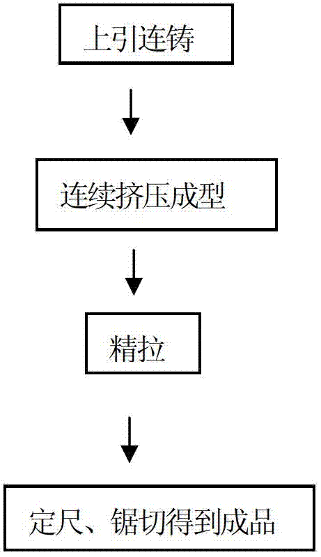
Continuous production technique of special-shaped hollow current conducting plates for electrolysis
A production process and conductive plate technology, applied in the field of continuous production process, can solve problems such as complex production process, difficult control of product quality, large raw material inventory, etc., to improve the yield and product quality, improve productivity and the economy of the enterprise Benefits, the effect of shortening the production cycle
- Summary
- Abstract
- Description
- Claims
- Application Information
AI Technical Summary
Problems solved by technology
Method used
Image

Examples
Embodiment 1
[0068] As shown in Figure 5(a)-(c), the structure of this embodiment is figure 2 The mold schematic diagram of the product, a product forming cavity is opened in the product mold 11, one end of the product forming cavity is the product mold outlet 10, and the other end of the product forming cavity 16 is the product mold inlet 12; the product forming cavity is a transition cavity Body 16 and forming section cavity 17 combined structure, the product mold inlet 12 is located at the outer end of the transition section cavity 16, the transition section cavity 16 adopts a horn-shaped transition structure, and a mold corresponding to the product conductive rib is set in the product forming cavity Conductive rib 13.
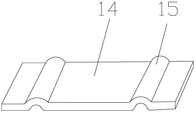
[0069] This embodiment adopts a fully automatic production line to produce special-shaped hollow conductive plates for electrolysis (see attached figure 2 ), there are two conductive bars 15 on the product 14 (conductive plate). The preparation process is as follows:...
Embodiment 2
[0083] The difference from Embodiment 1 is that, as shown in Figure 6(a)-(c), the structure of this embodiment is image 3 The mold schematic diagram of the product, a product forming cavity is opened in the product mold 11, one end of the product forming cavity is the product mold outlet 10, and the other end of the product forming cavity 16 is the product mold inlet 12; the product forming cavity is a transition cavity Body 16 and forming section cavity 17 combined structure, the product mold inlet 12 is located at the outer end of the transition section cavity 16, the transition section cavity 16 adopts a horn-shaped transition structure, and a mold corresponding to the product conductive rib is set in the product forming cavity Conductive rib 13.
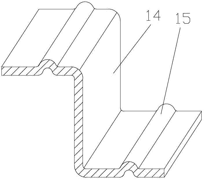
[0084] This embodiment adopts a fully automatic production line to produce special-shaped hollow conductive plates for electrolysis (see image 3 ), the plate is bent twice, and the transition between the two parallel flat plat...
Embodiment 3
[0098] The difference from Embodiment 1 is that, as shown in Figure 7(a)-(c), the structure of this embodiment is Figure 4 The mold schematic diagram of the product, the product mold 11 has a product forming cavity, one end of the product forming cavity is the product mold outlet 10, and the other end of the product forming cavity 16 is the product mold inlet 12; the product forming cavity is a transition cavity Body 16 and forming section cavity 17 combined structure, the product mold inlet 12 is located at the outer end of the transition section cavity 16, the transition section cavity 16 adopts a horn-shaped transition structure, and a mold corresponding to the product conductive rib is set in the product forming cavity Conductive rib 13.
[0099] This embodiment adopts a fully automatic production line to produce special-shaped hollow conductive plates for electrolysis (see Figure 4 ), the plate is bent, the cross-section is right-angled, and the product 14 is provided ...
PUM
 Abstract
Description
Claims
Application Information