

Continuous electric explosive spraying device for hole inner wall wires
A technology of spraying device and electric explosion, applied in coating, melting spraying, metal material coating process and other directions, can solve the problem of inability to obtain coating, and achieve the effects of low cost, high spraying efficiency and simple production
Inactive Publication Date: 2013-01-09
LANZHOU UNIVERSITY OF TECHNOLOGY
View PDF4 Cites 11 Cited by
- Summary
- Abstract
- Description
- Claims
- Application Information
AI Technical Summary
Problems solved by technology
Method used
View moreImage
Smart ImageViewing Examples

Examples
Embodiment Construction
Login to View More PUM
| Property | Measurement | Unit |
|---|---|---|
| length | aaaaa | aaaaa |
| diameter | aaaaa | aaaaa |
| diameter | aaaaa | aaaaa |
Abstract
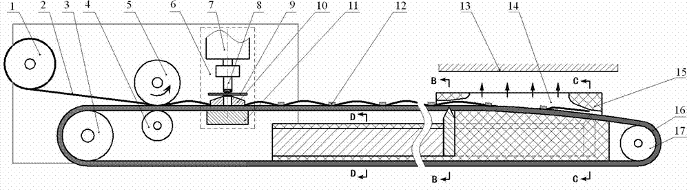
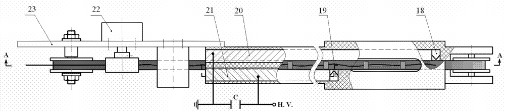
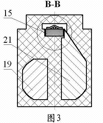
A continuous electric explosive spraying device for hole inner wall wires comprises a long electric-conducting support body, a drive mechanism and an electric explosive chamber. One end of the long electric-conducting support body is connected with two poles of a high-voltage energy accumulator (C), the other end of the long electric-conducting support body is provided with the explosive chamber (15), the explosive chamber (15) extends into a base body tubular cavity (13) along with the long electric-conducting support body, metal wires (2) are continuously transmitted by the drive mechanism into the explosive chamber (15) so as to enable a positive pole (18) and a negative pole (19) to explode in a high-voltage electric field, an explosive product is jetted onto an inner wall of the base body tubular cavity (13) along a jetting window (14) at the ultra-high speed, and continuous electric explosion and directional spraying of the hole part inner wall wires are achieved.
Description
technical field [0001] The invention relates to an electric explosion spraying equipment. Background technique Electric explosion spraying is to apply a DC high voltage to the metal conductor instantaneously, forming a huge current density inside the metal conductor, causing it to explode in a short time, and the explosive products are sprayed at a very high speed under the impact of the explosion, and then Rapid cooling on the substrate forms a coating with excellent mechanical properties. Electric explosion spraying has the advantages of wide application of materials and high energy conversion rate, and is especially suitable for the coating preparation of the inner surface of hole parts. At present, most of the electric explosion spraying equipment on the inner wall of the hole is to first place the metal wire, foil or powder on the central axis of the hole, and then turn on the high voltage switch to apply high voltage to the electrode to realize the electric explosi...
Claims
Login to View More Application Information
Patent Timeline
 Patent Type & AuthorityApplications(China)
IPC IPC(8): C23C14/48C23C4/08C23C4/126
Inventor朱亮赵进峰
OwnerLANZHOU UNIVERSITY OF TECHNOLOGY