Micro-explosion atomization oil gun

An oil gun and micro-explosion technology, applied in the field of oil gun and micro-explosive atomization oil gun, can solve the problems of affecting complete combustion, large atomization particle size, and increased pollution discharge, and achieve improved combustion efficiency and small atomization particle size. , the effect of reducing pollutants

Inactive Publication Date: 2013-01-09
徐州艾迪科技有限公司
View PDF5 Cites 7 Cited by
  • Summary
  • Abstract
  • Description
  • Claims
  • Application Information

AI Technical Summary

Problems solved by technology

Due to the need for high-pressure steam, the energy consumption is high, and because the mixing time of steam and oil is very short, some oil particles will enter combustion before they are fully atomized, affecting complete combustion, and the preheating of steam to oil is not enough, so preheating is required to ignite and work fine
[0005] Due to the defects of the principle and structure of these two types of oil guns, and the poor quality of fuel oil in my country, these two types of oil guns generally have the problem of large atomization particle size. Difficulty in directly igniting heavy residue oil and other problems, unable to meet the requirements of efficient and complete combustion, energy saving and emission reduction
Due to the low atomization quality of the oil gun and the insufficient combustion of the combustion oil, in order to ensure the normal temperature rise and process requirements of the heat-using equipment, the enterprise has to increase the amount of fuel injection, which directly increases the production and use costs of the enterprise, resulting in energy waste and pollution. Emissions increase; in addition, the coking and blockage of the oil gun is serious, and the incompletely burned oil droplets also directly affect the operation of related supporting equipment

Method used


Image

  • Micro-explosion atomization oil gun

Examples


Embodiment Construction

[0014] The present invention will be further described below in conjunction with accompanying drawing.

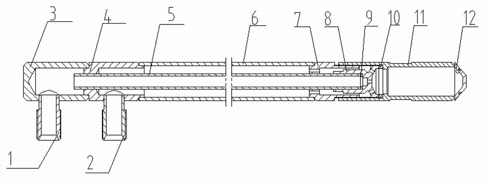
[0015] Such as figure 1 The present invention shown includes an oil interface 1, an air interface 2, an oil chamber 3, and an air chamber 4. The oil chamber 3 communicates with the oil interface 1, the air chamber 4 communicates with the air interface 2, and the oil chamber 3 communicates with the inner pipe 5 , the air chamber 4 communicates with the outer pipe 6, and the front ends of the inner pipe 5 and the outer pipe 6 are provided with a flow mixer 8, and the flow mixer 8 communicates with the front end of the inner pipe 5 through a small copper pad 9, and the flow mixer 8 communicates with the front end of the inner pipe 5 through an air pipe joint 7. The front end of the outer tube 6 communicates, the front end of the flow mixer 8 connects with the premixing chamber 11 through a large copper pad 10 , and the atomizing head 12 communicates with the front end of the p...


PUM


Abstract

The invention discloses a micro-explosion atomization oil gun, belonging to the field of thermal energy power. The micro-explosion atomization oil gun comprises an oil interface, a gas interface, an oil chamber and a gas chamber, wherein the oil chamber is communicated with the oil interface; the gas chamber is communicated with the gas interface; the oil chamber is communicated with an inner tube; the gas chamber is communicated with an outer tube; flow mixers are arranged at the front ends of the inner tube and the outer tube; the flow mixers are communicated with the front end of the inner tube through a small copper pad; the flow mixers are communicated with the front end of the outer tube through an air pipe interface; the front ends of the flow mixers are connected with a premixing chamber through a larger copper pad; and an atomization head is communicated with the front end of the premixing chamber. The micro-explosion atomization oil gun has the beneficial effects of small automation granularity and combustion sufficiency, so that the combustion efficiency is increased, the combustion oil is saved, the pollutants in combustion products are reduced, and the automation head is unlikely to be blocked and coked.

Description

technical field [0001] The invention relates to an oil gun, in particular to a micro-explosion atomization oil gun, which belongs to the field of thermal power. Background technique [0002] At present, the oil guns widely used in my country's oil burners are mainly divided into two categories: mechanical atomization and medium atomization. They are all oil guns that use a single atomization principle. [0003] The mechanical atomizing oil gun is mainly composed of a swirl atomizing sheet and an oil separator. Its working principle is that the oil with pressure passes through the oil inlet hole on the oil separator and merges into the corresponding circular groove, and then passes through the tangential groove on the swirl sheet to tangentially It flows into the swirl chamber to generate a strong rotation, and finally enters the atomizing sheet, and is ejected through the central nozzle hole of the atomizing sheet to form a hollow conical atomizing airflow composed of liquid...

Claims


Application Information

Patent Timeline
Patent Type & Authority Applications(China)
IPC IPC(8): F23D11/10F23D11/36
Inventor 李克新孙援
Owner 徐州艾迪科技有限公司
Why Eureka
Try Eureka