Thermal network modeling method applied to electric spindle steady temperature field

A modeling method and thermal network technology, which is applied in the field of thermal network modeling of the steady-state temperature field of an electric spindle, and can solve problems such as the influence of core heat sources on heat transfer.

Active Publication Date: 2013-01-09
XI AN JIAOTONG UNIV
View PDF2 Cites 35 Cited by
  • Summary
  • Abstract
  • Description
  • Claims
  • Application Information

AI Technical Summary

Problems solved by technology

[0006] In the existing literature, there is a lack of specifications for the refinement of the local thermal network for the lubrication and heat dissipation of the electric spindle ceramic hybrid ball bearing, the heat dissipation of the spiral cooling water, the layout of the motor nodes, and the heat distribution.
At the same time, the contact thermal resistance of the bearing contact part is ignored, which has a great influence on the heat transfer of the core heat source

Method used


Image

  • Thermal network modeling method applied to electric spindle steady temperature field
  • Thermal network modeling method applied to electric spindle steady temperature field
  • Thermal network modeling method applied to electric spindle steady temperature field

Examples


Embodiment Construction

[0017] An embodiment of the present invention will be further elaborated below in conjunction with the accompanying drawings: the present invention discloses a thermal network modeling method applied to the steady-state temperature field of an electric spindle, comprising the following steps:

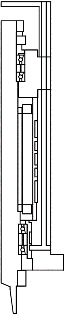
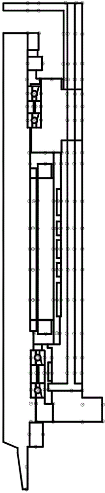
[0018] Step 1: Establish a 2D model of the shaft system

[0019] In the drawing software, establish a two-dimensional axisymmetric model of the shaft system (see figure 1 ). Each part of the main shaft generates a temperature gradient along the radial direction, and the circumferential temperature tends to be consistent; each part is symmetrical about the center line of the shaft, so that it is not necessary to consider the heat transfer in the circumferential direction; for small-sized chamfering fillets, bolt screw holes, Lead holes, oil holes, springs of the pre-tightening mechanism, sealing ring grooves at both ends of the cooling water jacket, gratings and speed sensors, and some ...


PUM


Abstract

The invention discloses a thermal network modeling method applied to an electric spindle steady temperature field. The method comprises the following steps of (1) building an electric spindle axisymmetric two-dimensional model; (2) building an equivalent thermal network of an axis; (3) calculating the overall heating value of a bearing and a motor, and distributing the heat to heating nodes; (4) according to heat transfer theory empirical formulas under different radiation conditions, calculating a convective heat transfer coefficient for heat exchange between a boundary node and fluid; (5) equalizing heat transfer between the nodes into ideal geometric heat transfer, obtaining conduction heat resistance of each part and boundary thermal-convection resistance, and building a heat transfer physical model; and (6) building a mathematical model and selecting a solution algorithm. A thermal network method is applied to a high-speed main shaft system with two heat sources, i.e. the bearing and the motor, and a complex convective heat exchange boundary, so that the difficulty in solving the characteristic temperature of each part of a complex assembling body of the main shaft is reduced. Compared with the method of solving a heat transfer differential equation, the thermal network modeling method is a quick and accurate steady temperature field calculation method.

Description

【Technical field】 [0001] The invention relates to a thermal network method, in particular to a thermal network modeling method applied to the steady-state temperature field of an electric spindle. 【Background technique】 [0002] The electric spindle is the main heat source and core component of high-speed machine tools. The axial thermal elongation and thermal deformation of bearing parts caused by temperature gradient will seriously affect the machining accuracy of machine tools and bearing preload. Therefore, the thermal characteristic analysis of the electric spindle is one of the key technologies to improve the precision of the machine tool. [0003] The electric spindle system includes two major heat sources: the friction heat generated by the spindle bearing and the loss heat generated by the embedded motor. The internal heat generation is large, and the heat transfer and heat dissipation process is complicated. In the spindle design stage, accurate calculation of the...

Claims


Application Information

Patent Timeline
Patent Type & Authority Applications(China)
IPC IPC(8): G06F17/50
CPCY02T10/82
Inventor 洪军王梦茜吴文武郭俊康刘光辉
Owner XI AN JIAOTONG UNIV
Why Eureka
Try Eureka