Phase-locked loop frequency synthesizer and phase-locked loop loss lock detecting and adjusting method

A technology of frequency synthesizer and phase-locked loop, applied in the direction of automatic power control, electrical components, etc., can solve the problems of increased switching noise, phase-locked loop loss of lock, inaccurate counting, etc., so as to reduce the time of coarse adjustment and avoid Energy increase, interference reduction effect

Active Publication Date: 2013-01-09
GUANGZHOU RUNXIN INFORMATION TECH
View PDF8 Cites 35 Cited by
  • Summary
  • Abstract
  • Description
  • Claims
  • Application Information

AI Technical Summary

Problems solved by technology

[0005] However, in the PLL out-of-lock detection stage, the existing practice is to set up a digital detection circuit to continuously detect the difference between the count value of the feedback clock in each set period and the predetermined number of times, and within a certain set period When the difference is greater than the set threshold, it is judged that the phase-locked loop is out of lock, and then the phase-locked loop frequency synthesizer re-enters the open-loop coarse adjustment stage
[0006] This method of using a digital detection circuit to determine whether the phase-locked loop is out of lock will lead to two disadvantages: one is that the digital detection circuit will increase the switching noise and cause reference harmonics; the other is to redo the open loop after the phase-locked loop is out of lock Modulation takes a long time
In addition, because the open-loop coarse tuning can work accurately only on the premise that the reference clock and the feedback clock are stable, but actually the reference clock and the feedback clock are not stable when the frequency synthesizer 100 is powered on, if the unstable reference clock Counting under the conditions of the feedback clock and the feedback clock will inevitably lead to inaccurate counting. Although the open-loop coarse adjustment can be performed after waiting for a certain period of time for the reference clock and the feedback clock to stabilize, this time cannot be controlled. It may be long or short. It also takes too long to re-do the open-loop coarse tuning

Method used


Image

  • Phase-locked loop frequency synthesizer and phase-locked loop loss lock detecting and adjusting method
  • Phase-locked loop frequency synthesizer and phase-locked loop loss lock detecting and adjusting method
  • Phase-locked loop frequency synthesizer and phase-locked loop loss lock detecting and adjusting method

Examples


Embodiment Construction

[0024] Below, in conjunction with accompanying drawing and specific embodiment, the present invention is described further:

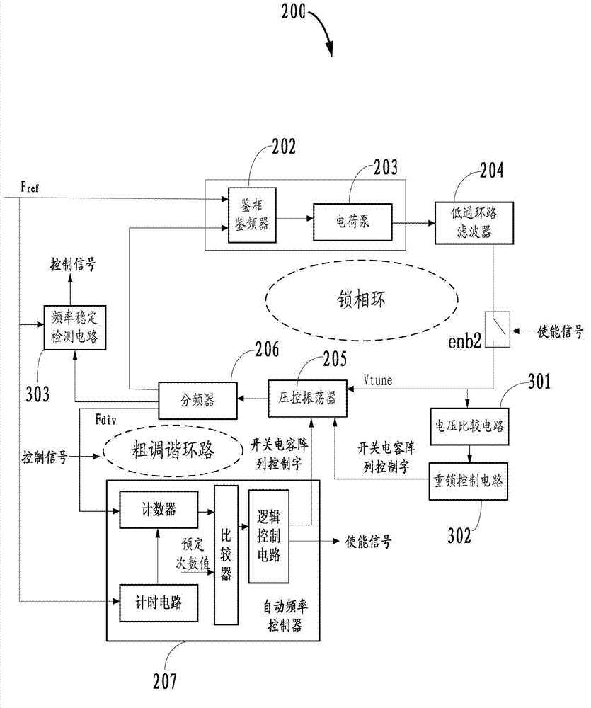
[0025] Such as figure 2 As shown, the structure of the phase-locked loop frequency synthesizer 200 of the present invention is roughly the same as that of the prior art, yet, one input terminal of the phase-frequency detector 202 is connected to the reference signal, and the other input terminal is connected to one of the frequency dividers 206 Output end, the input end of the counter of automatic frequency controller 207 connects the other output end of frequency divider 206, the frequency division ratio of frequency divider 206 in the stage of open-loop frequency coarse adjustment is the same as that of frequency divider 206 in the stage of closed-loop fine adjustment The frequency division ratio is different, that is, the frequency divider 206 is fed back to the feedback frequency Fdiv in the counter of the automatic frequency controller 207 in the ...


PUM


Abstract

The invention discloses a phase-locked loop frequency synthesizer which comprises a phase detection discriminator, a charge pump, a low-pass loop filter, a voltage controlled oscillator with a switched capacitor array, a frequency divider, an automatic frequency controller, a voltage comparison circuit and a relock control circuit, wherein the voltage comparison circuit judges whether tuning voltage Vtune output to the voltage controlled oscillator by the low-pass loop filter is in the preset voltage range in real time when the phase-locked loop frequency synthesizer is at the phase-locked loop loss lock detection stage; and the relock control circuit dynamically adjusts a value of a control word of the switched capacitor array of the voltage controlled oscillator according to the comparison result of the voltage comparison circuit. The invention also discloses a corresponding phase-locked loop loss lock detecting and adjusting method. By the phase-locked loop frequency synthesizer and the phase-locked loop loss lock detecting and adjusting method, increase of reference harmonic energy can be avoided; interference is reduced, and the coarse tuning time is shortened.

Description

[0001] technical field [0002] The invention relates to the field of wireless communication, in particular to a phase-locked loop frequency synthesizer and a phase-locked loop out-of-lock detection and adjustment method. [0003] Background technique [0004] The circuit diagram of a typical frequency synthesizer 100 based on a charge pump phase-locked loop is shown as figure 1 As shown, the frequency synthesizer 100 includes: a phase frequency detector (PFD) 102, a charge pump (CP) 103 (the phase frequency detector 102 and the charge pump 103 are integrated in one chip, and the chip can also include a internal low-pass loop filter (LPF), for optional use), low-pass loop filter (LPF) 104, voltage-controlled oscillator (VCO) 105, frequency divider (DIV) 106 and automatic frequency controller (AFC ) 107. In addition, a pre-frequency divider can also be set as required, and the reference signal can be frequency-divided by the pre-frequency divider. When the frequency synth...

Claims


Application Information

Patent Timeline
Patent Type & Authority Applications(China)
IPC IPC(8): H03L7/18H03L7/085H03L7/099
Inventor 王冬春李正平曾隆月
Owner GUANGZHOU RUNXIN INFORMATION TECH
Why Eureka
Try Eureka