Welding method for multi-layer metal strip

A multi-layer metal, welding method technology, applied in welding equipment, metal processing equipment, non-electric welding equipment, etc., can solve the problems of poor metal layer contact, consumption of large protective gas, easy burning of contact interface, etc., to achieve the production cycle Short, ensure electrical conductivity, improve the effect of production efficiency

Active Publication Date: 2013-01-16
NORTHWESTERN POLYTECHNICAL UNIV
View PDF8 Cites 23 Cited by
  • Summary
  • Abstract
  • Description
  • Claims
  • Application Information

AI Technical Summary

Problems solved by technology

The generation of these defects makes it possible to ensure the effective conductive area of ​​the joint only by increasing the number of layers of metal strips
In addition, the use of fusion welding technology for welding requires a lot of time to complete the preparation work before welding, and also consumes a lot of shielding gas, etc.
These not only seriously reduce the production efficiency, but also increase the production cost to a large extent
On the other hand, when bolted connection is used, the interface is easily oxidized due to the lack of close contact between the metal layers, and the contact interface is easily burned when the power is turned on.

Method used


Image

  • Welding method for multi-layer metal strip
  • Welding method for multi-layer metal strip

Examples


Embodiment Construction

[0021] Now in conjunction with embodiment, accompanying drawing, the present invention will be further described:

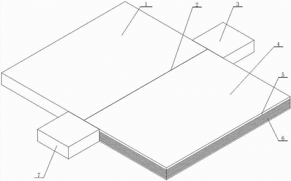
[0022] figure 1 It is a schematic diagram of the present invention: 1 is a metal plate sample or a sample formed by stacking multiple layers of metal strips, that is, 1 and 4 may be the same or different. 2 is the weld center line of the butt joint of the sample. 3 is the hole receiving plate, its function is to lead out the keyhole left on the sample when the welding is finished. According to actual process needs, if it is not necessary to lead out the keyhole left on the welded sample at the end of welding, the hole receiving plate is not required. The positions of plates 3 and 7 can be interchanged, and the materials can be different; 4 is stacking of multi-layer metal strips Formed welded samples. When the thickness of the metal strip is less than 1.0mm, 4 is composed of 5 and 6. 5 is a metal plate with a thickness of 1.0~4.0mm placed on the top layer, and...


PUM

PropertyMeasurementUnit
thicknessaaaaaaaaaa
thicknessaaaaaaaaaa
thicknessaaaaaaaaaa

Abstract

The invention relates to a welding method for a multi-layer metal strip. The method is characterized by comprising the following steps of: stacking the multi-layer metal strip to be welded to reach the required thickness, and aligning the multi-layer metal strip with the weld of another stacked multi-layer metal strip or metal plate; fixing a welding guiding plate of which the thickness is the same as that of the multi-layer metal strip to be welded at the starting end of a weld joint along the welding direction; selecting a stirring head, wherein the diameter of a shaft shoulder of the stirring head is 2 to 3 times the plate thickness, the length of a stirring needle on the stirring head is 0.05 to 0.2mm less than the plate thickness, and the press amount of the shaft shoulder is 0.1 to 0.3mm; and selecting rotation speed and welding speed according to a welding material, and welding. The method is energy-saving and environment-friendly, an operation process is greatly simplified, and production efficiency is improved; the quality of a joint is improved, the conductivity of the joint is ensured, and production cost is reduced; controllability is high, and industrial application is easy to implement; and the obtained joint has a compact structure, does not have any pore or crack and is slightly deformed, the operation process is simple, the production period is short, efficiency is high, and the production cost is low.

Description

technical field [0001] The invention relates to a welding method for multilayer metal strips, which is suitable for the connection between multilayer metal strips and between multilayer metal strips and metal plates. The method has the advantages of simple operation process, low production cost, high efficiency, high joint quality, good reliability and easy popularization and application. Background technique [0002] Metal strips (such as aluminum strips, copper strips) have good plasticity, electrical conductivity, thermal conductivity, and easy bending and deformation. An important part in the production of high-end devices such as rectifiers and their installation. Therefore, in the field of electronics industry, a large number of connections between multi-layer metal strips and other components are involved. This connection can adjust equipment installation errors, shock absorption, and facilitate testing and equipment maintenance. At present, this kind of connection ...

Claims


Application Information

Patent Timeline
Patent Type & Authority Applications(China)
IPC IPC(8): B23K20/12
Inventor 李文亚张志函高大路
Owner NORTHWESTERN POLYTECHNICAL UNIV
Why Eureka
Try Eureka