Method for calibrating ellipsometer with phase compensator

An ellipsometer and phase compensator technology, applied in the direction of measuring the polarization of light, instruments, scientific instruments, etc., can solve the problems of low precision, complexity, and the error between the actual angle and the angle that needs to be set, so as to improve the measurement accuracy, The effect of simplifying the measurement process and the simple calibration process

Inactive Publication Date: 2013-01-16
INST OF MICROELECTRONICS CHINESE ACAD OF SCI +1
View PDF7 Cites 28 Cited by
  • Summary
  • Abstract
  • Description
  • Claims
  • Application Information

AI Technical Summary

Problems solved by technology

Because in the above-mentioned calibration method, it is generally necessary to rotate the polarizer P electrically or manually, and after determining the polarization direction of the polarizer, it is also necessary to manually or electrically rotate the polarizer to a certain angle required, the mechanical structure is unstable and or human error will cause the error between the actual angle and the angle that needs to be set, resulting in the inaccuracy of the sample measurement. Therefore, in the prior art, the calibration method of the polarizer angle is relatively low in accuracy. This limits the measurement accuracy of the ellipsometer
[0007] The angle of incidence in the ellipsometer can be obtained by manual measurement, but due to the limited accuracy of manual measurement

Method used


Image

  • Method for calibrating ellipsometer with phase compensator
  • Method for calibrating ellipsometer with phase compensator
  • Method for calibrating ellipsometer with phase compensator

Examples


Embodiment 1

[0125] The angle calibration method of Embodiment 1 of the present invention is described below through specific steps, which can be divided into the following steps:

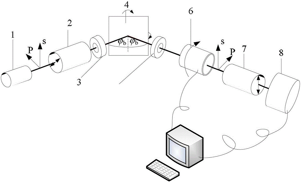
[0126] (1) Fix the polarizer and analyzer in the ellipsometer. Since the ellipsometer has high measurement accuracy at certain polarizer angles, before the measurement, the polarizer (including polarizer and analyzer) with known approximate transmission direction can be rotated to a suitable angle and fixed. For example, the angles between their transmission directions and the incident surface of the light beam on the sample are 45° and 22.5° respectively (actually due to the low accuracy of the transmission direction of the polarizer and operational errors, the transmission of the polarizer The vibration direction angle is hardly really on these two polarizer angles, but around here).

[0127] (2) Measure the first reference sample: Rotate the compensator at a constant speed, load the first reference sample w...

Embodiment 2

[0132] The angle calibration method of Embodiment 2 of the present invention is illustrated below through specific steps, which can be divided into the following steps:

[0133] (1) Fix the polarizer and phase compensator in the ellipsometer.

[0134] (2) Measure the first reference sample: Rotate the analyzer at a constant speed, load the first reference sample with known optical constants and thicknesses (n1, k1, d1), measure through the above ellipsometry, and obtain the light intensity curve I 1 (t).

[0135] (3) Measure the second reference sample: load the second reference sample with known optical constant and thickness (n2, k2, d2), repeat the measurement in step 2, and obtain the light intensity curve I 2 (t).

[0136] (4) Obtain experimental Fourier coefficients through Fourier expansion: According to the light intensity curve obtained from the above measurement, Fourier expansion or fitting can be performed to obtain two sets of Fourier coefficient values ​​(α' 2...


PUM


Abstract

The invention discloses a method for calibrating a polarization angle of an ellipsometer with a phase compensator in an ellipsometry system, a phase delay angle of the phase compensator and a light incidence angle of the ellipsometer, and belongs to the technical field of optical measuring instruments. The method is characterized in that correction values of working parameters of the ellipsometer with the phase compensator are obtained by fitting via a least square method according to experimental Fourier coefficients, optical constants and a deduced relational expression among theoretical Fourier coefficients and the working parameters of the ellipsometer. By the method, system parameters including polarization directions of a polarizer and a polarization analyzer, the delay angle of the phase compensator and the light incidence angle of the ellipsometer with the phase compensator can be calibrated, a calibrating process is simple and accurate, the ellipsometer can be directly used for measuring without adjusting components of the system after calibration is completed, accordingly, a measuring process is simplified, and measurement precision is improved.

Description

technical field [0001] The present invention relates to the technical field of optical measuring instruments, in particular to a calibration of the polarization direction, the fast (slow) axis direction of the phase compensator, the delay angle of the phase compensator, and the incident light angle in an ellipsometry system including a phase compensator method. Background technique [0002] With the rapid development of the semiconductor industry, it is very important to use optical measurement technology to accurately measure the critical dimension (Critical Dimension), spatial morphology and material properties of the three-dimensional structure formed by single-layer or multi-layer thin films on the wafer. For the measurement results to be valid, the measurement system used should be able to measure film thickness and / or film composition with high accuracy. At present, the well-known non-destructive detection technology, ellipsometry, obtains the characteristic parameter...

Claims


Application Information

Patent Timeline
IPC IPC(8): G01B11/06G01N21/21G01J4/00
Inventor 徐鹏王林梓刘涛刘健鹏李国光
Owner INST OF MICROELECTRONICS CHINESE ACAD OF SCI
Why Eureka
Try Eureka