Device and method for detecting light

A technology for detecting light and spectrometers, applied in measuring devices, using electric radiation detectors for photometry, and using methods for comparing with reference electrical parameters, etc., can solve problems such as expensive design of photomultiplier tubes

Active Publication Date: 2013-01-16
LEICA MICROSYSTEMS CMS GMBH
View PDF6 Cites 15 Cited by
  • Summary
  • Abstract
  • Description
  • Claims
  • Application Information

AI Technical Summary

Problems solved by technology

[0007] Photomultiplier tubes have a more expensive design compared to detectors fabricated using Si technology
Also, for example, photomultiplier tubes typically have lower photon detection efficiencies than avalanche photodiodes

Method used


Image

  • Device and method for detecting light
  • Device and method for detecting light
  • Device and method for detecting light

Examples


Embodiment Construction

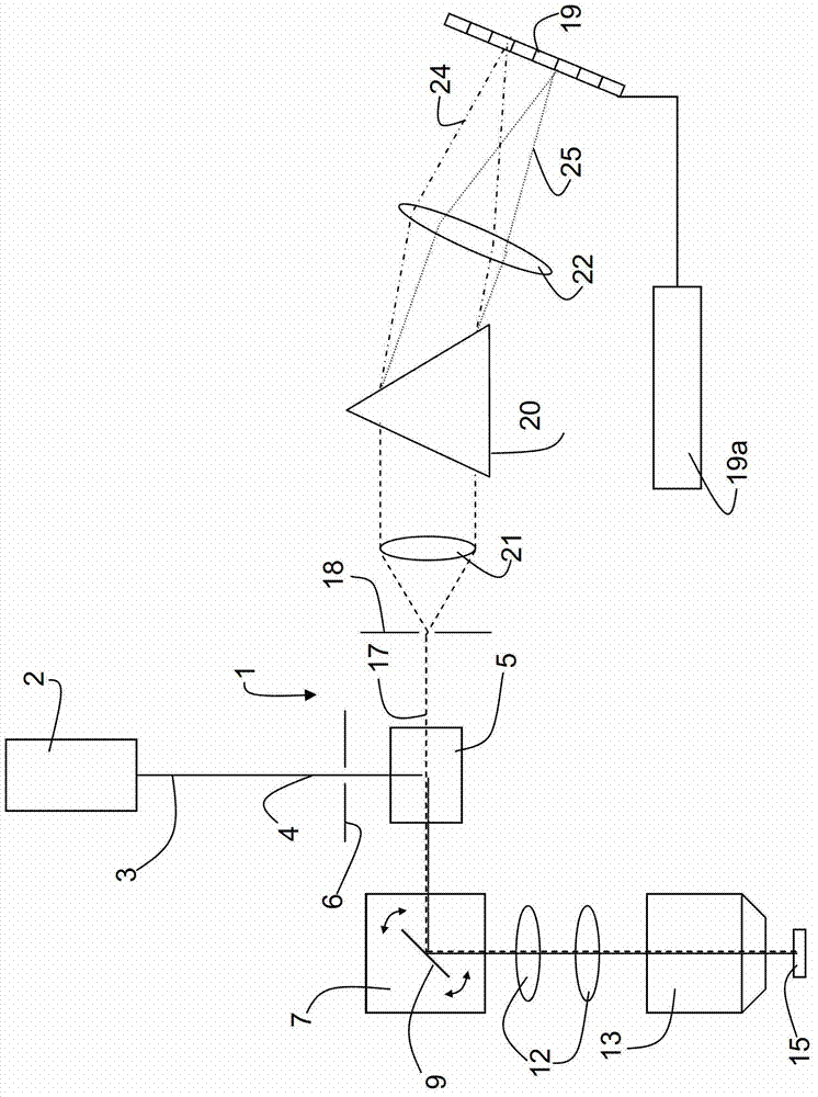
[0048] Based on the example of a confocal scanning microscope, figure 1 The use of a device according to the invention to detect probe light returning from a sample is shown. Particularly, figure 1 A schematic configuration of a confocal scanning microscope 1 is shown, wherein an array 19 of SPADs 26 is used to detect signals from the scanning microscope 1 . The illuminating beam 3 from the light source 2 is directed to the scanning device 7 via a beam splitter or a suitable optical path deflecting device 5 . Before reaching the optical path deflecting device 5 , the illuminating light beam 3 passes through the illuminating aperture 6 .

[0049] In this embodiment, the scanning device 7 comprises a gimbaled scanning mirror 9 which projects the illumination beam 3 through the scanning optics 12 and the microscope optics 13 onto or through the object 15 . In the case of a non-transparent object 15, the illumination beam 3 is directed onto the object surface. In the case of l...


PUM


Abstract

A device for detecting light includes at least one silicon photomultiplier (SiPM) having an array of a plurality of single-photon avalanche diodes (SPADs), the array being larger in area than an incident light. The device is configured so as to at least one of activate and analyze only the SPADs upon which a specific minimum intensity of light impinges.

Description

technical field [0001] The invention relates to devices for detecting light, in particular for use in microscopes, spectrometers or cameras. The invention also relates to a corresponding method which is preferably carried out using the device. Background technique [0002] In general terms, the focus of the invention is the detection of light, for example as used in microscopes, spectrometers or cameras. The claimed apparatus is not limited to a particular application. In a broad sense, it should be understood as a photodetector. [0003] Known in the art for many years, a photomultiplier tube (PMT) is a special type of electron tube that detects weak light signals or even single photons by generating and amplifying light signals. Photomultiplier tubes typically consist of a photocathode arranged in a vacuum glass tube and a downstream secondary electron multiplier tube. Since the photomultiplier tube is a vacuum tube, its size is relatively large, so it is not suitable ...

Claims


Application Information

Patent Timeline
Patent Type & Authority Applications(China)
IPC IPC(8): G01J1/42G01J1/04
CPCG01J3/027G01J1/44G01J1/18G01J3/2803G01J3/36G01J1/0228G02B21/008
Inventor H·比尔克V·塞弗里德
Owner LEICA MICROSYSTEMS CMS GMBH
Why Eureka
Try Eureka