System and method for quickly positioning noise source through image identification and sound intensity scanning

An image recognition and positioning system technology, which is applied in positioning, radio wave measurement system, surveying and navigation, etc., can solve the problems of measuring point positioning, inconvenient engineering application, and low efficiency that do not involve image recognition technology, so as to reduce the difficulty of testing and complexity, facilitate engineering applications, and improve the effect of precision

Inactive Publication Date: 2013-01-16
SHANGHAI JIAO TONG UNIV
View PDF8 Cites 14 Cited by
  • Summary
  • Abstract
  • Description
  • Claims
  • Application Information

AI Technical Summary

Problems solved by technology

However, none of these patents involves the use of image recognition technology to locate the spatial position of the measuring point, and their inventions only involve methods related to mechanical structure design in detection equipment
Moreover, in the above-mentioned devices and methods of the prior art, there is no description on how to use a fast positioning method to determine the position of the measurement point. During the measurement, the measurement position needs to be set in advance, and the measurement position is recorded after each measurement. This method Not convenient for engineering application, low efficiency

Method used


Image

  • System and method for quickly positioning noise source through image identification and sound intensity scanning
  • System and method for quickly positioning noise source through image identification and sound intensity scanning

Examples


Embodiment 1

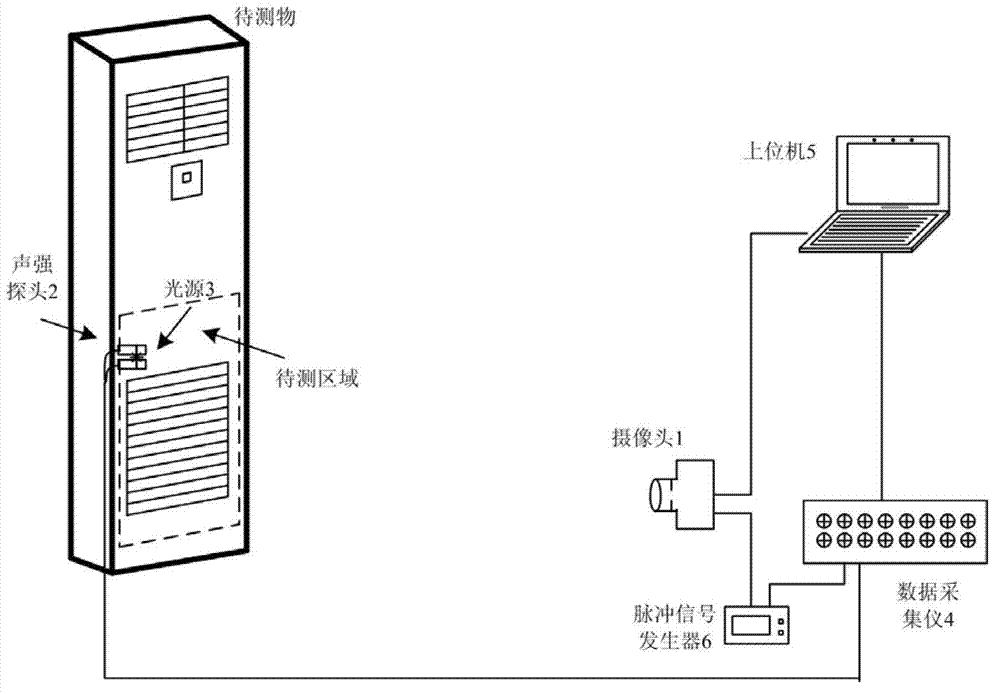
[0050] Please also refer to figure 1 , a method for quickly locating noise sources using image recognition and sound intensity scanning, comprising the following steps:

[0051] 1. Take the indoor unit of the vertical air conditioner as the sound source to be tested, detect the sound field distribution in the lower half of the area, adjust the position and focal length of the camera 1 so that the area captured includes the area to be tested, and connect the signal of the camera 1 to the host computer 5 interface, take an image and save it in the host computer 5 as a background image.

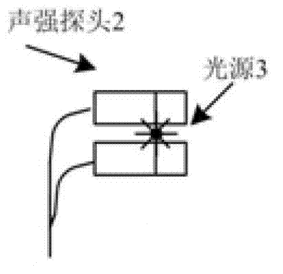
[0052] 2. Fix the light-emitting diode as the light source 3 near the sound intensity probe 2, use battery power to make it emit light, and connect the signal wire of the sound intensity probe 2 to the data acquisition instrument 4. The host computer 5 performs light filtering processing, so that the color of the light source 3 is highlighted in the image captured by the camera 1, and other col...


PUM


Abstract

The invention discloses a system and a method for positioning a noise source. The method comprises the following steps of: adjusting the position and focal length of a camera until a taken image comprises a region to be detected, and storing an image which is taken as a background image into an upper computer; fixing a light source on a sound intensity probe which is connected with a data acquirer; endowing the image which is taken by the camera with the color of a light source by filtering; moving the sound intensity probe, and scanning on the surface of the region to be detected at constant speed; outputting a trigger signal by a pulse signal generator, continuously taking images by the camera, recording a motion image of the light source, recording the trigger signal and an acoustic signal by the data acquirer, and synchronizing the acoustic signal and image taking time; after detection is finished, processing the image, and thus obtaining the position of the light source in a picture; extracting the acoustic signal, and thus obtaining acoustic physical quantity information at a corresponding moment; dividing the region to be detected into triangular units, wherein nodes are the positions of the light source, which are acquired at all moments, and the acquired acoustic physical quantity serves as a cloud picture measuring value; and acquiring a sound field cloud picture, and displaying the sound field cloud picture. The invention has the advantages of quick positioning, accurate measurement and high accuracy.

Description

technical field [0001] The invention relates to a noise source location method, in particular to a noise source rapid location system and method using image recognition and sound intensity scanning. Background technique [0002] In order to effectively control noise, before noise reduction measures are implemented, noise source diagnosis must be carried out first to determine the location and characteristics of each major noise source. With the development of modern signal processing technology, spectral analysis technology, coherent and partial coherent analysis technology, sound intensity detection technology, beam forming, and near-field acoustic holography technology have been developed rapidly. [0003] Among these methods, the sound intensity detection technology has become a low-cost and high-efficiency tool in the noise source localization method because it uses fewer sensors and is easy to operate. The sound intensity detection technology determines the direction o...

Claims


Application Information

Patent Timeline
Patent Type & Authority Applications(China)
IPC IPC(8): G01S5/18G01C11/00
Inventor 张海滨严莉蒋伟康陈晓波
Owner SHANGHAI JIAO TONG UNIV
Why Eureka
Try Eureka