
Camera body structure for temperature adaptive space remote-sensing camera

A remote-sensing camera and self-adaptive technology, which is applied to the camera body, camera, optics, etc., can solve the problems such as the position change of optical components is out of tolerance, and achieve the effect of improving reliability, wide temperature adaptation range, and reducing related requirements

Active Publication Date: 2013-01-16
CHANGCHUN INST OF OPTICS FINE MECHANICS & PHYSICS CHINESE ACAD OF SCI
View PDF5 Cites 3 Cited by
  • Summary
  • Abstract
  • Description
  • Claims
  • Application Information

AI Technical Summary

Problems solved by technology

However, this method requires stricter temperature control, and there is still the possibility that the position of the optical element will change out of tolerance

Method used


Image

  • Camera body structure for temperature adaptive space remote-sensing camera

Examples


Embodiment Construction

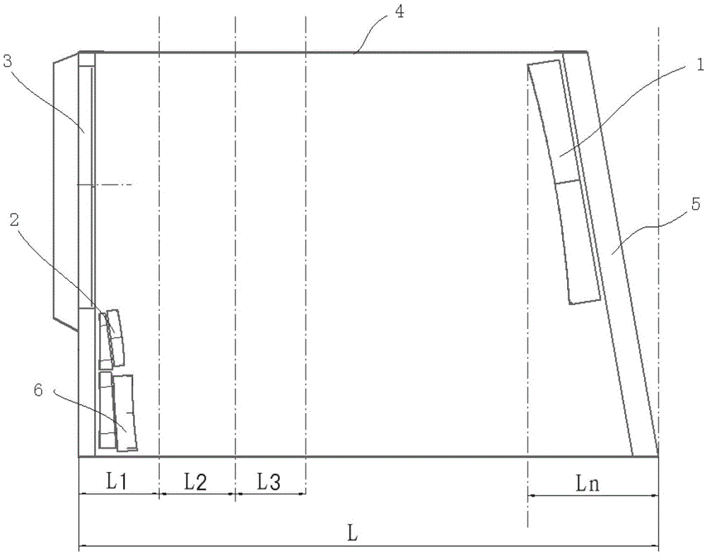
[0023] Such as figure 1 As shown, the aerospace remote sensing camera body is mainly composed of a front frame 3, a bearing tube 4, a rear frame 5, a primary mirror 1, a secondary mirror 2, and a third mirror 6. The materials of the primary mirror 1, the secondary mirror 2 and the third mirror 6 can be flexibly selected according to actual needs, and silicon carbide materials or other materials with better thermal stability are used; the front frame 3, the bearing tube 4 and the rear frame 5 are all made of M40J Carbon fiber composite material or other types of carbon fiber composite material. The front frame 3 and the rear frame 5 are respectively connected with the bearing cylinder 4 by glue screws to form an integral carbon fiber fuselage structure. The front frame 3 and the rear frame 5 can also adopt other materials according to actual needs. The load-bearing cylinder 4 is composed of n sections of carbon fiber composite materials with different thermal linear expansion...


PUM


Abstract

The invention relates to a camera body structure for a temperature adaptive space remote-sensing camera. The structure comprises a primary mirror, a secondary mirror, three mirrors, a front frame, a bearing cylinder and a rear frame, wherein the bearing cylinder consists of n sections of carbon fiber composite materials with different hot line expansion coefficients. The overall equivalent hot line expansion coefficients of the bearing cylinder are changed, and the hot line expansion coefficients of the primary mirror, the secondary mirror, the front frame, the bearing cylinder and the rear frame are reasonably designed, so that the position variation between the primary mirror and the secondary mirror is always 0 regardless of the temperature change. By the camera body structure, the problem that the temperature adaptive space remote-sensing camera is low in dimensional stability in the spatial thermal environment is effectively solved, so that the camera has a wide temperature adaptation range, the related requirements on thermal control are reduced, and the reliability of a remote-sensing camera system is improved.

Description

Technical field: [0001] The invention belongs to the technical field of optical precision machinery and relates to a space remote sensing camera, in particular to a body structure of a temperature adaptive space remote sensing camera. Background technique: [0002] With the development of space remote sensing technology, human beings have higher and higher demand for planetary observation. The volume and quality of space remote sensing cameras are increasing with the resolution. In order to ensure the imaging quality, the dimensional stability of the structure is particularly important. The body of an aerospace remote sensing camera is mainly composed of a front frame, a load-bearing cylinder, a rear frame, a primary mirror, a secondary mirror, and a third mirror. Since remote sensing cameras need to work in a space thermal environment, improper thermal control measures will inevitably lead to changes in the structure of the camera's optical system, resulting in relative pos...

Claims


Application Information

Patent Timeline
Patent Type & Authority Applications(China)
IPC IPC(8): G03B17/02
Inventor 郭疆朱磊齐洪宇杨劲松
Owner CHANGCHUN INST OF OPTICS FINE MECHANICS & PHYSICS CHINESE ACAD OF SCI
Learn More