
Simulation method for gas static pressure main shaft dynamic predication

A technology of gas static pressure and simulation method, applied in the field of dynamic simulation, can solve the problems of low precision, difficult modeling, difficult prediction of dynamic characteristics of the main shaft, etc., and achieve the effect of accurate prediction of dynamic characteristics

Active Publication Date: 2015-03-04
HARBIN INST OF TECH
View PDF2 Cites 0 Cited by
  • Summary
  • Abstract
  • Description
  • Claims
  • Application Information

AI Technical Summary

Problems solved by technology

[0003] In order to solve the problem of difficult modeling and low precision of the traditional simulation method in the prior art, it is difficult to predict the dynamic characteristics of the main shaft in the design stage, thereby providing a simulation method for the dynamic prediction of the aerostatic main shaft

Method used


Image

  • Simulation method for gas static pressure main shaft dynamic predication
  • Simulation method for gas static pressure main shaft dynamic predication
  • Simulation method for gas static pressure main shaft dynamic predication

Examples


specific Embodiment approach 1

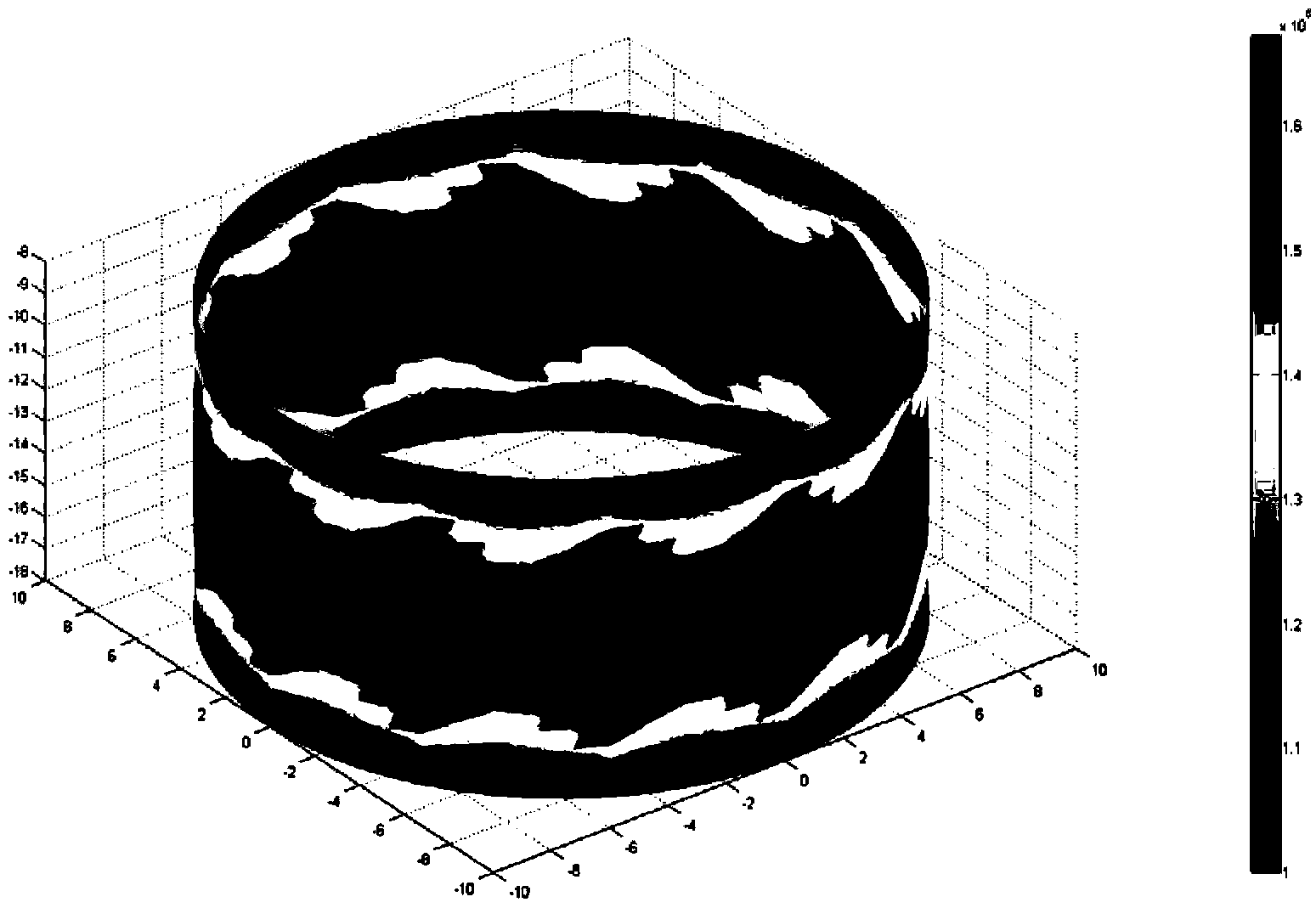
[0019] Specific implementation mode 1. Combination Figure 1-7 Describe this specific embodiment, this specific embodiment is the simulation method that is used for aerostatic spindle dynamics prediction, and its steps are as follows:

[0020] Step 1: Using the finite element method and the principle of gas static pressure, the gas static pressure spindle bearing gas film is divided into finite element grids, and the pressure distribution data We of the gas static pressure spindle is calculated; the gas static pressure spindle includes the gas static pressure Spindle bearing air film and gas static pressure spindle shaft body;

[0021] Step 2: Establish a corresponding finite element model of the main shaft body according to the finite element grid obtained in step 1, and the finite element model represents the solid unit of the aerostatic main shaft body;

[0022] Step 3: Convert the pressure distribution data We of the finite element principal axis obtained in step 1 into a...

specific Embodiment approach 2

[0026] Embodiment 2. This embodiment is different from Embodiment 1 in that step 1 of the simulation method for the dynamics prediction of the gas static pressure spindle utilizes the finite element method and the principle of gas static pressure, through the analysis of the gas static pressure spindle The bearing gas film is divided into finite element grids, and the method of calculating the pressure distribution data We of the gas static pressure spindle is as follows:

[0027] Applying the Reynolds equation to calculate the pressure distribution of the air film of the aerostatic spindle bearing, the Reynolds equation is Formula 1:

[0028] ∂ ∂ x ( h 3 p ∂ p ∂ x ) + ∂ ...

specific Embodiment approach 3

[0047] Specific Embodiment 3. The difference between this specific embodiment and specific embodiment 1 is that in the step 3 of the simulation method for dynamics prediction of the gas static pressure spindle, the pressure distribution data We of the finite element spindle obtained in step 1 are transformed into is the equivalent spring stiffness value, and assigns the equivalent spring stiffness value to the node corresponding to the gas film finite element grid, the process of obtaining the equivalent spring element is:

[0048] Step 3A converts the pressure distribution data We of the finite element spindle obtained in step 1 into a stiffness value through formula 5;

[0049] K e = ∂ W ‾ e ∂ h formula five

[0050] Where Ke is the stiffness value of the ga...


PUM


Abstract

The invention relates to a simulation method for gas static pressure main shaft dynamic predication, and the method can be used for solving the problems of modeling difficulty, and difficulty in predicating the dynamic characteristics of the main shaft at the design stage due to low precision of a traditional method in the prior art. The method comprises the following steps of: partitioning a gas static pressure main shaft bearing gas film into finite element grids by utilizing a finite element method and a gas static pressure theory, and calculating to obtain the pressure distribution data We of a gas static pressure main shaft; establishing a finite element model, corresponding to the finite element grids, of a main shaft body; converting the pressure distribution data We of the finite element main shaft into equivalent spring stiffness values and assigning the equivalent spring stiffness values to nodes corresponding to the finite element grids of the gas film; and establishing a finite element model of the gas static pressure main shaft, and calculating the dynamic characteristics of the gas static pressure main shaft according to the established finite element model. The method is mainly used for predicating the dynamic characteristics of the gas static pressure main shaft.

Description

technical field [0001] The invention relates to a simulation method for dynamics prediction of an aerostatic spindle, belonging to the field of dynamics simulation. Background technique [0002] As a key component of the machine tool, the spindle drives the tool or workpiece to rotate to achieve material removal. Its dynamic and static performance directly determines the machining accuracy of the workpiece. In recent years, air spindles have attracted widespread attention due to their high speed, high precision, and low heat generation. However, the dynamic modeling and simulation in the design process of the aerostatic spindle is the key to the design of the entire aerostatic bearing, but the traditional simulation method in the prior art has problems such as difficult modeling and low precision, which will cause the spindle to be affected in the design stage. Difficult problems in predicting dynamic properties. Contents of the invention [0003] In order to solve the p...

Claims


Application Information

Patent Timeline
Patent Type & Authority Patents(China)
IPC IPC(8): G06F17/50
Inventor 梁迎春陈万群孙雅洲刘海涛孙阳安晨辉
Owner HARBIN INST OF TECH
Learn More