
Photoelectric mixed connector

An optoelectronic hybrid and connector technology, which is applied in the direction of connection, components and circuits of connecting devices, can solve the problems of complex structure, inability to arrange the high-voltage insertion interface, and difficulty in controlling the force at the high-voltage insertion interface. Compact and reasonable layout

Active Publication Date: 2013-01-16
中国电子科技集团公司第四十研究所
View PDF3 Cites 17 Cited by
  • Summary
  • Abstract
  • Description
  • Claims
  • Application Information

AI Technical Summary

Problems solved by technology

Photoelectric hybrid connector is an organic combination of high-voltage connectors, low-voltage connectors and optical fiber connectors. It has a larger volume and a more complex structure.
[0003] When the mating interface is small (such as when the diameter of the interface used to arrange the corresponding components on the plug mounting board and the socket mounting board is only 17.8 mm, and the axial space is only 4 mm), if the mounting boards are separately arranged pin components or sockets Hole components, it is impossible to realize the spatial position
Unless the mating interface is layered (that is, divided into a high-voltage mating interface and a low-voltage mating interface), the layered structure also has the following defects: 1. Difficulties in mold design, especially for the installation of silicone rubber materials 2. Because the layout interface is too small, the high-voltage mating interface cannot be arranged in a circular shape, and the force at the high-voltage mating interface is difficult to control

Method used


Image

  • Photoelectric mixed connector
  • Photoelectric mixed connector
  • Photoelectric mixed connector

Examples


Embodiment Construction

[0044] Embodiments of the present invention will be specifically described below in conjunction with the accompanying drawings:

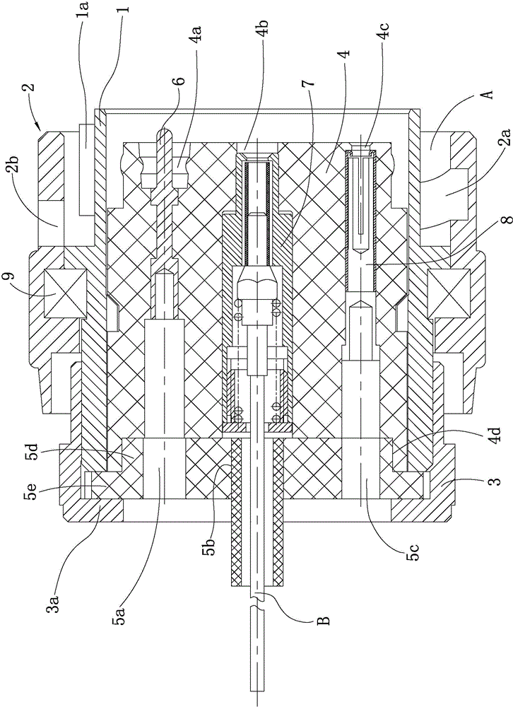
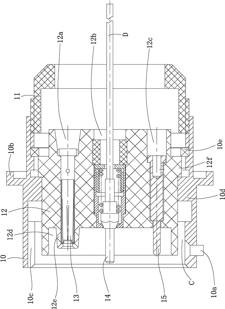
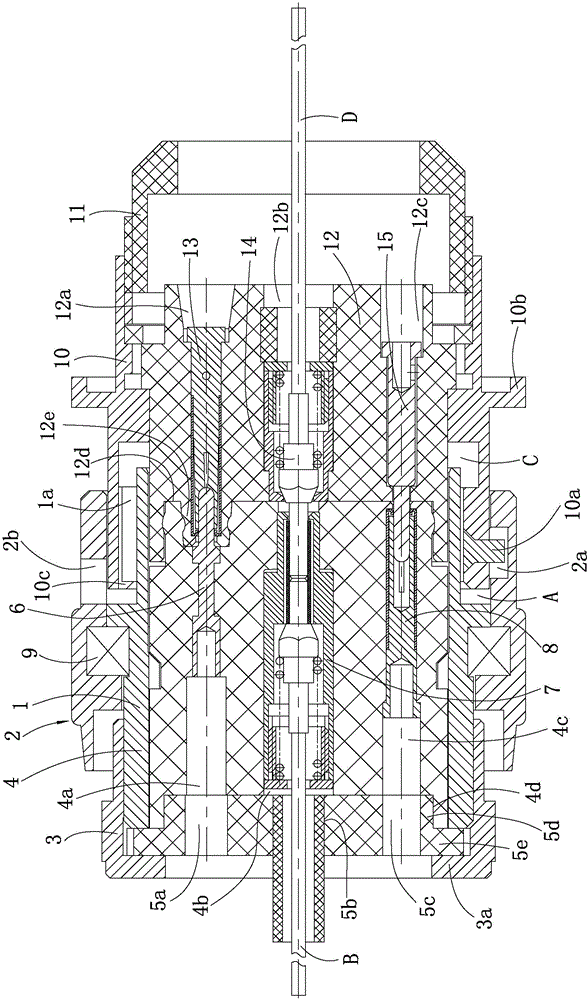
[0045] see figure 1 - Figure 5 :

[0046] This connector consists of a plug and a socket.

[0047] The structure of the plug itself and the connection between parts are as follows:

[0048] The plug includes a plug housing 1, a connecting sleeve 2, a nut 3, a circular plug mounting plate 4, a baffle plate, four high-voltage pin assemblies 6 respectively used to connect the high-voltage wires of the plug, and an optical fiber used to connect the optical fiber wire B of the plug. Jack assembly 7, seven low-voltage jack assemblies 8 respectively used to connect plug low-voltage wires. The cross section of the inner cavity of the plug housing 1 is circular, and the cross section of the connecting sleeve 2 is circular. For the sake of succinctly explaining the problem, the high-voltage wires of the plug and the low-voltage wires of the plug are not...


PUM


Abstract

The invention discloses a photoelectric mixed connector. The photoelectric mixed connector comprises a plug and a socket, wherein the plug comprises a plug shell, a connecting sleeve, a nut, a plug installation plate, a baffle, a plurality of high-voltage plug pin components, at least one optical fibre plug hole component and a plurality of low-voltage plug hole components; the socket comprises a socket shell, an encapsulation sleeve, a socket installation plate, a plurality of high-voltage plug hole components, at least one optical fibre plug pin component and a plurality of low-voltage plug pin components; a second installation hole is positioned in the central area of the plug installation plate; a first installation hole and a third installation hole are close to the outer edge of the plug installation plate and are respectively positioned on the two sides of the second installation hole; an eighth installation hole is positioned in the central area of the socket installation plate; and a seventh installation hole and a ninth installation hole are close to the outer edge of the socket installation plate and are respectively positioned on the two sides of the eighth installation hole. By the connector, the high-voltage components, the low-voltage components and the optical cable components also can be organically combined together on the premise that installation space is smaller; and the actual application under related conditions is met.

Description

technical field [0001] The invention relates to a connector, in particular to a photoelectric hybrid connector integrating optical fiber communication, power transmission and signal control. Background technique [0002] At present, the photoelectric hybrid connector is mainly used for power supply in electronic equipment, data connection of electrical and optical signals, it not only has high-voltage components and low-voltage components, but also includes optical fiber components. The photoelectric hybrid connector is an organic combination of high-voltage connectors, low-voltage connectors and optical fiber connectors. It has a large volume and a complex structure. [0003] When the mating interface is small (such as when the diameter of the interface used to arrange the corresponding components on the plug mounting board and the socket mounting board is only 17.8 mm, and the axial space is only 4 mm), if the mounting boards are separately arranged pin components or socke...

Claims


Application Information

Patent Timeline
IPC IPC(8): H01R13/502H01R13/40H01R13/631G02B6/38
Inventor 彭光辉王小波王强王虹张小平
Owner 中国电子科技集团公司第四十研究所
Learn More