Waste gas filtering equipment

A waste gas filtration and equipment technology, which is applied in the direction of dispersed particle separation, chemical instruments and methods, combined devices, etc., can solve the problems of untreated, reduced filtering effect, and low service life, so as to reduce waste and pollution of water resources, equipment, etc. The effect of low investment cost and long service life

Inactive Publication Date: 2013-01-23
BLACK GOLD STEEL AUTOMATION TECH FUJIAN
View PDF4 Cites 6 Cited by
  • Summary
  • Abstract
  • Description
  • Claims
  • Application Information

AI Technical Summary

Problems solved by technology

[0004] There are many disadvantages in the above-mentioned technical solution. First, the structure is complicated, the precision requirement is high, it is easy to be damaged, the service life is low, and the production cost is increased; secondly, the equipment does not use circulation filtration, and the filtration effect of the filter layer will decrease obviously after a period of use. To achieve the expected effect, at the same time, the wastewater in the filter pool group has not been treated, which will not only increase the cost, but also cause waste and pollution of water resources

Method used


Image

  • Waste gas filtering equipment
  • Waste gas filtering equipment

Examples


Embodiment approach 1

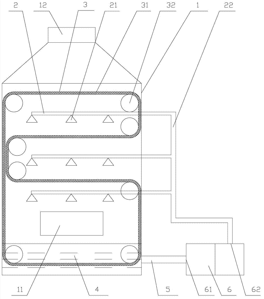
[0013] Implementation Option 1: Reference figure 1 , The filter equipment includes a main box 1, a spray cooling system 2, a three-stage filter system 3, a scrubbing water tank 4, and an oil-water separation treatment circulating water tank 6. The main box contains an air inlet 11 and an air outlet 12 . The spray cooling system 2, the three-stage filter system 3 and the scrubbing water tank 4 are all located in the main box body 1, and the scrubbing water tank 4 is located below the main box body 1; the spray cooling system includes a spray rack 21 and a water supply pipe 22, The filter system includes a drum 32 and a filter cloth curtain 31. The spray frame of the spray cooling system is located under each layer of filter cloth curtain 31 in the filter system. The drum 32 is distributed on the two side walls of the main box 1, and the filter cloth curtain 31 is wound back and forth. Set on the drum 32, the two drums 32 located at the bottom of the two side walls are connecte...

Embodiment approach 2

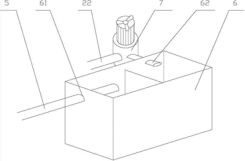
[0015] Implementation Option 2: Reference figure 1 , figure 2 , The filter equipment includes a main box 1, a spray cooling system 2, a three-stage filter system 3, a scrubbing water tank 4, and an oil-water separation treatment circulating water tank 6. The main box contains an air inlet 11 and an air outlet 12 . The spray cooling system 2, the three-stage filter system 3 and the scrubbing water tank 4 are all located in the main box body 1, and the scrubbing water tank 4 is located below the main box body 1; the spray cooling system includes a spray rack 21 and a water supply pipe 22, The filter system includes a drum 32 and a filter cloth curtain 31. The spray frame of the spray cooling system is located under each layer of filter cloth curtain 31 in the filter system. The drum 32 is distributed on the two side walls of the main box 1, and the filter cloth curtain 31 is wound back and forth. Set on the drum 32, the two drums 32 located at the bottom of the two side walls...


PUM


Abstract

The invention discloses waste gas filtering equipment, which comprises a main box, a spray cooling system, a filtering system, a scrubbing water box and an oil and water separation circulating water box, wherein the main box comprises a gas inlet and a gas outlet, and the scrubbing water box is positioned on the lower part of the main box; the spray cooling system comprises spray frames, the filtering system comprises rollers and a filtering cloth curtain, the spray frames of the spray cooling system are respectively positioned below the filtering cloth curtain of the filtering system, the rollers are arranged on two side walls of the main box, and the filtering cloth curtain is wound on the rollers back and forth; the two rollers positioned on the lowermost parts of the two side walls are connected with a power system, and the filtering cloth curtain passes through the scrubbing water box; and the scrubbing water box is connected with the oil and water separation circulating water box through a return water pipe. The waste gas filtering equipment has the advantages of simple structure and low equipment investment cost, a circulating and filtering system is adopted, hairs, spandex oil and air particle impurities in waste gas can be effectively removed, and the waste gas filtering efficiency is improved.

Description

technical field [0001] The invention relates to an exhaust gas treatment system, in particular to an exhaust gas filtering device. Background technique [0002] Waste gas treatment refers to the pretreatment of waste gas generated in industrial sites and factory workshops before being discharged to the outside, so as to meet the national standards for external discharge of waste gas. At present, the spray towers used by exhaust gas filtration equipment in the traditional market are only equipped with baffles in the tower body to allow exhaust gas to pass through, and sprinklers are installed above the baffles. This type of waste gas filtration equipment only performs simple and rough filtration on the waste gas, and can only filter out large particles of waste residue, but cannot effectively filter out small particles of impurities in the waste gas. Secondly, for different types of waste gas, especially complex and difficult Filtered exhaust gas cannot achieve satisfactory ...

Claims


Application Information

Patent Timeline
Patent Type & Authority Applications(China)
IPC IPC(8): B01D50/00
Inventor 阙小鸿
Owner BLACK GOLD STEEL AUTOMATION TECH FUJIAN
Why Eureka
Try Eureka