Drying equipment

A technology for drying equipment and cabinets, applied in the field of mechanical equipment, can solve problems such as easy cracking, shrinkage, affecting wood quality, and high energy consumption, so as to achieve suitable drying temperature, good drying effect, and water saving Effect

Active Publication Date: 2015-06-10
浦北县建业胶合板有限责任公司
View PDF9 Cites 2 Cited by
  • Summary
  • Abstract
  • Description
  • Claims
  • Application Information

AI Technical Summary

Problems solved by technology

[0002] Existing drying equipment, such as the Chinese utility model patent whose publication number is CN201992954U, is a multifunctional wood vacuum automatic drying equipment, which includes a drying system, a steam system, a heating system, a vacuum system and a dehumidification system. The system feeds hot air into the drying system to dry the wood in the drying system, and then feeds steam according to the dryness and humidity of the wood, which can dry the wood at any time, which solves the problem that the wood cannot be dried due to climate reasons, but It uses a heating system to heat the air, which consumes a lot of energy, and the drying system cannot effectively adjust its heating temperature according to the degree of wood drying, and the quality of the dried wood is not good; in addition, the high-temperature air of the heating system is directly passed into the drying system , due to the relatively low equilibrium moisture content in the drying process, the moisture content gradient on the cross-section of the wood is steep, and it is easy to form drying defects such as cracks and shrinkage, which will affect the quality of the wood; moreover, such drying equipment is not suitable for other drying of items

Method used


Image

  • Drying equipment

Examples


Embodiment Construction

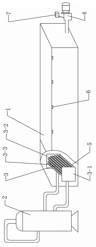
[0022] Such as figure 1 As shown, a drying device of the present invention includes a drying box 1 and a heat source generating device 2. An air inlet is provided on the upper front end of the drying box 1, and a heat exchanger 3 is arranged at the air inlet. It flows into the drying box 1 through the heat exchanger 3 . The heat exchanger 3 includes an inlet pipe 3-1, an outlet pipe 3-2 and a plurality of heat exchange pipes 3-3, the heat source generator 2 is connected to the inlet of the inlet pipe 3-1, and the outlet of the inlet pipe 3-1 is connected to the inlet of the inlet pipe 3-1. The inlets of the heat exchange pipes 3-3 are connected, and the outlets of the heat exchange pipes 3-3 are connected with the inlets of the outlet pipes 3-2; the air outlet at the rear end of the drying box is connected with an induced draft fan 4 for leading the air flow out of the box.

[0023] The heat exchange tubes 3-3 are seamless tubes, which are parallel to each other and arranged ...


PUM


Abstract

The invention discloses drying equipment, comprising a drying box body and a heat source generating device, wherein an air inlet is formed at the front end of the drying box body; the air inlet is provided with a heat exchanger; the heat exchanger comprises a leading-in pipe, a leading-out pipe and a plurality of heat exchanging pipes; the heat source generating device is connected with an inlet of the leading-in pipe and an outlet of the leading-in pipe is communicated with inlets of the heat exchanging pipes; outlets of the heat exchanging pipes are communicated with an outlet of the leading-out pipe; and a rear end air outlet of the drying box is connected with an induced draft fan for leading an air flow out of the box body. The drying equipment utilizes steam to carry out heat exchange to dry cargoes; the energy consumption is low and the drying temperature is moderate; particularly, the drying temperature for drying wood sheets cannot be too high and the balanced water content in a drying process is relatively lower when the drying temperature is too high; and the water content slope of the cross section of a wood is more abrupt and drying defects of cracks, wrinkles and the like are easy to form, so as to influence the quality of a wood sheet.

Description

technical field [0001] The invention relates to a mechanical device for drying articles, in particular to a drying device for drying wood, cartons, baking paint and the like. Background technique [0002] Existing drying equipment, such as the Chinese utility model patent whose publication number is CN201992954U, is a multifunctional wood vacuum automatic drying equipment, which includes a drying system, a steam system, a heating system, a vacuum system and a dehumidification system. The system feeds hot air into the drying system to dry the wood in the drying system, and then feeds steam according to the dryness and humidity of the wood, which can dry the wood at any time, which solves the problem that the wood cannot be dried due to climate reasons, but It uses a heating system to heat the air, which consumes a lot of energy, and the drying system cannot effectively adjust its heating temperature according to the degree of wood drying, and the quality of the dried wood is ...

Claims


Application Information

Patent Timeline
Patent Type & Authority Patents(China)
IPC IPC(8): F26B15/00F26B21/00F26B25/00
Inventor 黄河
Owner 浦北县建业胶合板有限责任公司
Why Eureka
Try Eureka