U-shaped pipe type heat exchanger

A U-shaped tube and heat exchanger technology, applied in the field of U-shaped tube heat exchangers, can solve problems such as poor heat exchange effect, and achieve the effects of simple structure, convenient operation and good heat exchange effect.

Inactive Publication Date: 2013-01-23
TSUWA KOKI WUXI
View PDF2 Cites 3 Cited by
  • Summary
  • Abstract
  • Description
  • Claims
  • Application Information

AI Technical Summary

Problems solved by technology

The heat exchange effect of the existing heat exchanger is not good, the present

Method used


Image

  • U-shaped pipe type heat exchanger

Examples


Embodiment Construction

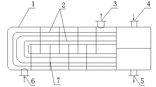
[0011] Such as figure 1 As shown, a U-shaped tube heat exchanger, the heat exchanger includes a shell 1, a U-shaped tube 2 and a partition 7, the shell is a hollow tank shape, and the U-shaped tube 2 is installed on In the housing 1, the two ports of the U-shaped pipe 2 correspond to the cold fluid inlet 4 and the cold fluid outlet 5 respectively; the partitions 7 are several, forming a hot fluid flow channel to realize the temperature cross-exchange of the hot and cold fluids.

[0012] The partitions 7 are installed on the top and the bottom of the casing 1, parallel and staggered.

[0013] The thermal fluid inlet 6 is at the bottom of the housing 1 , and the thermal fluid outlet 3 is at the top of the housing 1 .

[0014] The cold fluid inlet 4 communicates with the U-shaped pipe 2 , the inlet is at the top of the housing 1 , and the cold fluid outlet 5 is at the bottom of the housing 1 .

[0015] There are multiple U-shaped pipes 2 .

[0016] The U-shaped tube heat excha...


PUM


Abstract

The invention provides a U-shaped pipe type heat exchanger. The heat exchanger comprises a shell, a U-shaped pipe and a plurality of separation plates, wherein the shell is in a hollow pot body shape; the U-shaped pipe is mounted in the shell; two end openings of the U-shaped pipe respectively correspond to an outlet and an inlet of cold fluid; the plurality of the separation plates form a hot fluid flow channel so as to realize crossed heat exchange of the temperature of cold and hot fluid; the separation plates are mounted on the top of the shell and at the bottom of the shell and are parallel and staggered; an inlet of hot fluid is located at the bottom of the shell; and an outlet of the hot fluid is located at the top of the shell. The U-shaped pipe type heat exchanger disclosed by the invention is simple in structure and good in heat exchange effect, and is convenient to operate.

Description

technical field [0001] The invention relates to a U-shaped tube heat exchanger. technical background [0002] The heat exchange tube is one of the components of the heat exchanger, which is placed inside the cylinder and used for heat exchange between two media. In addition to bare tubes, heat exchangers can also use a variety of enhanced heat transfer tubes, such as finned tubes, threaded tubes, spiral grooved tubes, etc. When the heat transfer coefficient on both sides of the inner diameter of the tube differs greatly, the fins of the finned tube should be arranged on the side with the lower heat transfer coefficient. Commonly used materials are carbon steel, low alloy steel, stainless steel, copper, copper-nickel alloy, aluminum alloy, titanium, etc. In addition, there are some non-metallic materials, such as graphite, ceramics, polytetrafluoroethylene and so on. The heat exchange effect of the existing heat exchanger is not good, and the present invention relates to a...

Claims


Application Information

Patent Timeline
IPC IPC(8): F28D7/06
Inventor 喻一彰
Owner TSUWA KOKI WUXI
Why Eureka
Try Eureka