Optical oscillation device and recording apparatus

A technology for recording equipment and optics, applied in the field of recording equipment and optical oscillation devices, can solve the problems of proportional increase in high-frequency superposition circuits and cost increase

Inactive Publication Date: 2013-01-23
SONY CORP
View PDF4 Cites 2 Cited by
  • Summary
  • Abstract
  • Description
  • Claims
  • Application Information

AI Technical Summary

Problems solved by technology

However, this method can lead to an increase in device size proportional to the added high-frequency superposition circuit, which may lead to an increase in cost

Method used


Image

  • Optical oscillation device and recording apparatus
  • Optical oscillation device and recording apparatus
  • Optical oscillation device and recording apparatus

Examples


Embodiment Construction

[0041] Hereinafter, a recording apparatus according to an embodiment of the present invention and an example of a self-excited oscillation semiconductor laser used in the recording apparatus will be described with reference to the accompanying drawings. Embodiments of the present invention will be described in the following order. The present invention is not limited to the examples described below.

[0042] 1. Structure of self-excited oscillation semiconductor laser

[0043] 2. Construction of recording equipment

[0044] 1. Structure of self-excited oscillation semiconductor laser

[0045] First, the configuration of a self-excited oscillation semiconductor laser 1 according to an embodiment of the present invention will be described.

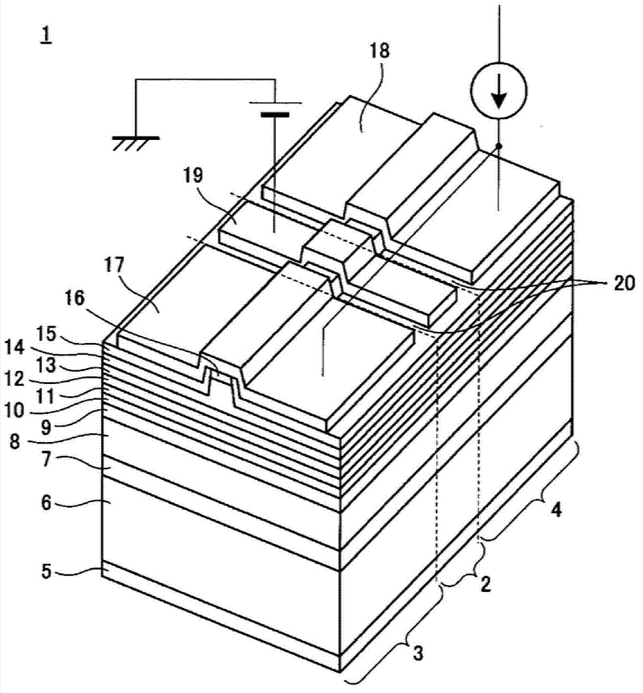
[0046] figure 1 is a schematic diagram showing the configuration of a self-excited oscillation semiconductor laser 1 according to an embodiment of the present invention. The self-excited oscillation semiconductor laser 1 is a self-excit...


PUM


Abstract

Provided is a recording apparatus including a self-excited oscillation semiconductor laser that has a double quantum well separate confinement heterostructure and includes a saturable absorber section to which a negative bias voltage is applied and a gain section into which a gain current is injected, an optical separation unit, an objective lens, a light reception element, a pulse detection unit, a reference signal generation unit, a phase comparison unit, a recording signal generation unit, and a control unit.

Description

technical field [0001] The present invention relates to an optical oscillation device emitting laser light and a recording apparatus using the same. Background technique [0002] In recent years, with the development of IT in society, larger capacity and higher speed communications are necessary. Therefore, as for the medium used to propagate information, not only the optical communication technology of radio waves with frequencies such as 2.4GHz band and 5GHz band in radio communication but also the band with wavelengths such as 1.5μm (up to hundreds of THz frequencies) are used The optical communication technology of light has rapidly entered into widespread use. [0003] For example, a method of transmitting information by light is used not only for optical communication such as optical fiber communication, but also for recording and reproducing information on / from a recording medium. Therefore, optical information technology will become an important basis for supportin...

Claims


Application Information

Patent Timeline
Patent Type & Authority Applications(China)
IPC IPC(8): G11B7/126G11B7/127H01S5/00H01S5/10
CPCH01S5/0658H01S5/34333H01S5/00H01S5/10G11B7/126H01S5/06253G11B7/1263G11B7/127B82Y20/00
Inventor 藤田五郎丸山务
Owner SONY CORP
Why Eureka
Try Eureka