A power connection device

A technology of power supply connection and electrical connector, applied in the field of power supply connection equipment, can solve the problems of power failure, state monitoring of equipment that cannot supply power, and high cost

Inactive Publication Date: 2016-03-16
LIRICCO TECH
View PDF7 Cites 1 Cited by
  • Summary
  • Abstract
  • Description
  • Claims
  • Application Information

AI Technical Summary

Problems solved by technology

[0003] Wireless networks generally use radio frequency transceivers (Radio Frequency Transceiver) to form a network with power supply equipment to monitor or control power supply equipment. The reliability of the connection transmission control signal will be reduced, resulting in delays and even system instability
[0004] Wired networks can lay special data lines between devices, for example, existing broadband network data lines, which require special planning and design during design, and require separate wiring during implementation, resulting in high costs, especially The renovation project for existing family houses is very difficult and even impossible
In addition, the wired network can also form a network through the power line between devices, that is, use power line communication, so that as long as the device is connected to the power supply, no separate wiring is required, but the existing home automation network using power line communication, one is to connect the power line As a broadband network, the network is only connected to the Internet; the other usually only uses the main control device to control the power consumption of the controlled device, such as a computer connected to the main control device, and a printer coupled to the computer, Peripherals such as scanners and stereos are connected to the controlled device, so that when the user powers off the computer, the master control device will control the controlled device to power off, that is, other peripherals will also be powered off at the same time
[0005] Through the research of the prior art, the inventor found that: compared with the radio frequency signal, although the home automation network using the power line communication does not need separate wiring, and the control signals will not interfere with each other, the reliability is high, but it can only realize the power supply The power supply mode of the equipment is controlled, that is, power-on or power-off control, but the status of each power supply equipment cannot be monitored, which cannot meet the needs of home automation

Method used


Image

  • A power connection device
  • A power connection device
  • A power connection device

Examples


Embodiment 1

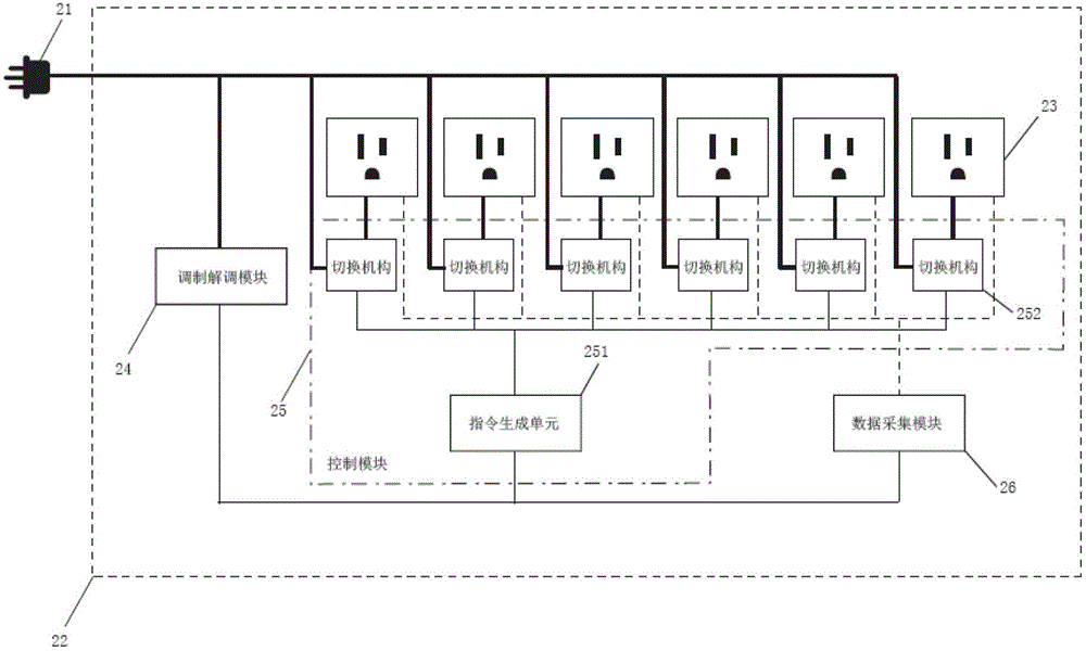
[0040] In order to enable devices in the home automation network to perform information exchange through power lines, an embodiment of the present application provides a power supply connection device.

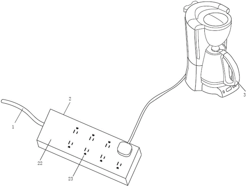
[0041] Such as figure 1 As shown, it is a schematic structural diagram of the power supply connection device provided by the embodiment of the present application when it is in use. In the figure, 1 is a power line, 2 is the power supply connection device, and 3 is an electrical device. When in use, the power supply connection device 2 is connected to the power line 1 through an electric wire, such as figure 1As shown, 22 in the figure is the casing of the power supply connection device, and at least one socket 23 is arranged on the casing 22, and the plug of the electric device 3 can be inserted into the socket 23 on the power supply connection device 2, so that The electrical equipment 3 is connected to the power line 1 , that is, the primary task of the power supply connec...

Embodiment 2

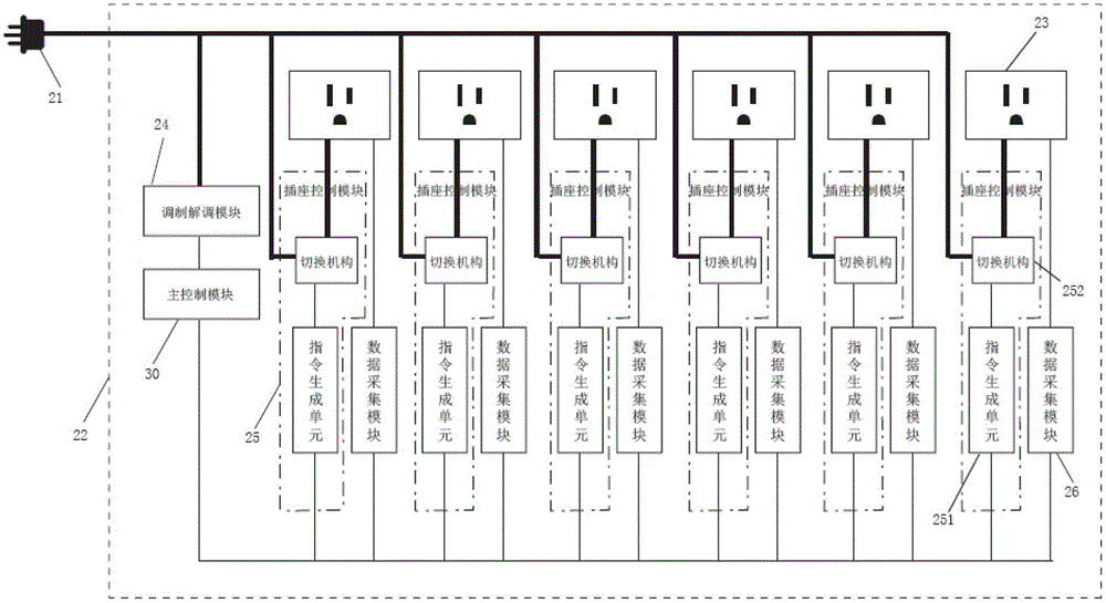
[0061] In the above-mentioned embodiments, the sockets only receive control signals from the power line. For users, on the basis of remote control of the sockets, they often need to temporarily control the sockets on site, for example: When removing the plug from the socket, the electrical equipment needs to be disconnected from the power supply. Therefore, the embodiment of the present application also provides another socket, so that the user can control the power supply connection device on site.

[0062] Figure 4 Another schematic structural diagram of the power supply connection device provided in the embodiment of the present application.

[0063] like Figure 4 As shown, the power supply connection device also includes: a human-computer interaction module 27, in the embodiment of the present application, the human-computer interaction module 27 includes: an input part 271 and a display part 272, wherein: the input part 271 is connected with the control module 25, It...

Embodiment 3

[0068] In the first embodiment above, it has been described that the power supply connection device provided by the embodiment of the present application can monitor the status of the power supply connection device remotely, and in order to further improve the intelligence of the power supply connection device, the power supply connection device Some abnormal situations can also be processed on the basis of the collected data. For this reason, this application also provides another power supply connection device, such as Figure 4 As shown, the power supply connection device further includes: an exception processing module 28 .

[0069] The exception processing module 28 is connected with the control module 25 and the data acquisition module 26 respectively, and is used to analyze the working state of at least one socket according to the data collected by the data collecting module 26, and when determining the working state of a socket 23 In case of abnormality, a control sign...


PUM


Abstract

A power supply connection device, including: an electric connector, a shell connected to the electric connector, and at least one socket disposed on the shell, and also including: a modulation / demodulation module, a control module and a data acquisition module, wherein the control module and the data acquisition module are separately connected to the at least one socket. The control module is used for controlling the ON or OFF of the socket according to a control signal. The data acquisition module is used for acquiring the ON or OFF state of the socket and operational parameters. The modulation / demodulation module is used for receiving a signal transmitted via an electric power line, extracting the control signal from the received signal and transmitting same to the control module, and receiving the data acquired by the data acquisition module, modulating the data acquired by the data acquisition module and then transmitting same to the electric power line. The power supply connection device provided in the present application can not only perform remote monitoring on the state of the power supply connection device, but can also perform remote control on the power supply connection device.

Description

technical field [0001] The present application relates to the technical field of electrical appliances, in particular to a power supply connection device. Background technique [0002] Existing home automation network, data transmission can be carried out through wireless network, wired network and wireless network. [0003] Wireless networks generally use radio frequency transceivers (Radio Frequency Transceiver) to form a network with power supply equipment to monitor or control power supply equipment. The reliability of the connection transmission control signal will be reduced, resulting in delays and even system instability. [0004] Wired networks can lay special data lines between devices, for example, existing broadband network data lines, which require special planning and design during design, and require separate wiring during implementation, resulting in high costs, especially The project of transforming the existing family house is very difficult and even impo...

Claims


Application Information

Patent Timeline
Patent Type & Authority Patents(China)
IPC IPC(8): H01R13/66H01R13/70G05B19/04G08C19/00
CPCG06F1/266G06F2200/261H01R13/70H01R25/003H02J13/00007H02J13/0005Y02B90/20Y02D10/00Y04S40/121
Inventor 李家俊伍薇
Owner LIRICCO TECH
Why Eureka
Try Eureka