Electromagnetic deicing system for high-voltage line insulator

A technology for high-voltage lines and insulators is applied in the field of removing ice on the surface of insulators of high-voltage lines to achieve the effects of high work efficiency, improved work efficiency and high degree of automation

Active Publication Date: 2020-09-29
STATE GRID HEILONGJIANG ELECTRIC POWER CO LTD ELECTRIC POWER RES INST +1
View PDF9 Cites 0 Cited by
  • Summary
  • Abstract
  • Description
  • Claims
  • Application Information

AI Technical Summary

Problems solved by technology

[0005] The purpose of the present invention is to solve the problem of how to provide a deicing device that does not affect the operation of the power grid, and provides an electromagnetic deicing system for high voltage line insulators

Method used


Image

  • Electromagnetic deicing system for high-voltage line insulator
  • Electromagnetic deicing system for high-voltage line insulator

Examples


specific Embodiment approach 1

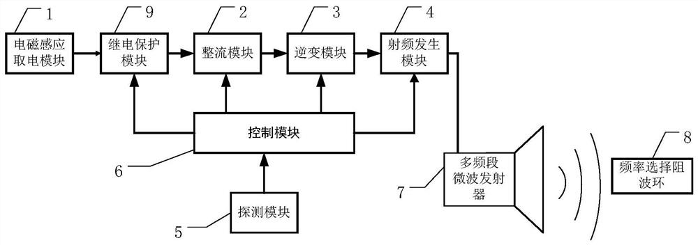
[0035] Specific implementation mode one: see figure 1 and figure 2 Describe this embodiment, an electromagnetic deicing system for high-voltage line insulators described in this embodiment, including an electromagnetic induction power acquisition module 1, a rectification module 2, an inverter module 3, a radio frequency generation module 4, a detection module 5, and a control module 6 , a multi-band microwave transmitter 7, M frequency-selective choke rings 8 and a relay protection module 9;

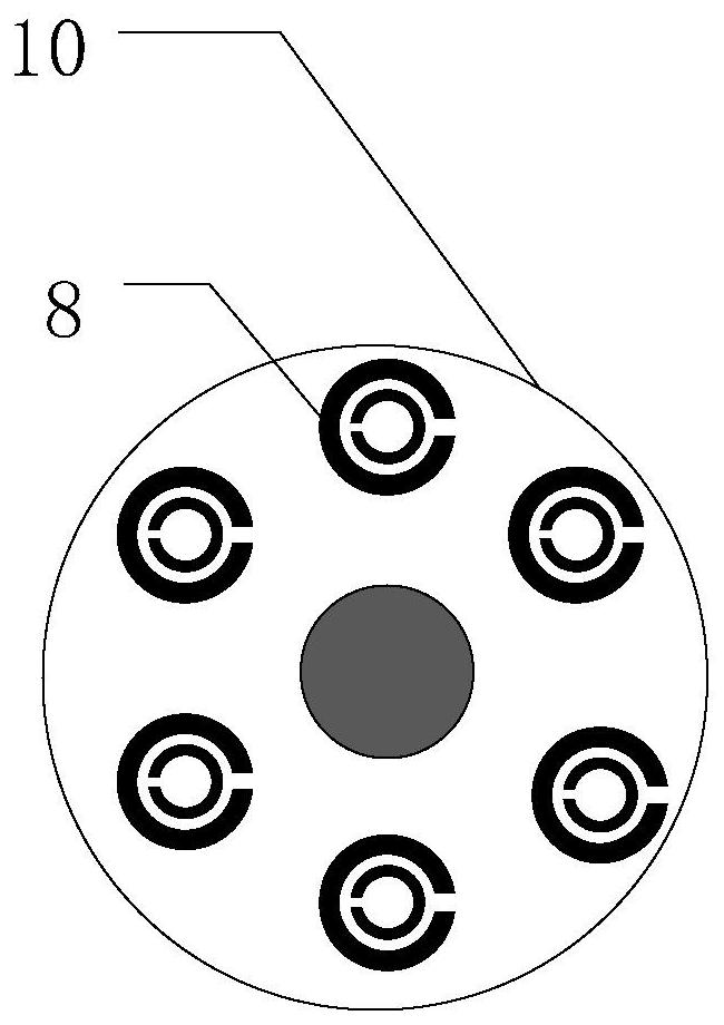
[0036] M frequency selective wave choke rings 8 are divided into N groups, and each group includes one or more frequency selective wave choke rings 8; N groups of frequency selective wave choke rings 8 are respectively arranged on N layers of insulating layers 10 of the insulator string; The frequency selective choke rings 8 on the same insulating layer 10 are used to receive electromagnetic waves in the same frequency band, and the frequency bands of electromagnetic waves received by...

specific Embodiment approach 2

[0047] Specific implementation mode two: for details, see figure 1 and figure 2 , this embodiment is a further description of the high-voltage line insulator string electromagnetic deicing system described in the first embodiment. The frequency selective wave choke ring 8 is made of semiconductor materials and has flexibility and stretchability;

[0048] There are two ways to fix the frequency selective choke ring 8 on the insulating layer 10 of the insulator string:

[0049] First, one end face of the frequency selective wave choke ring 8 can be adhered to the surface of the insulating layer 10 of the insulator string through adhesive glue, and then the other end face of the frequency selective wave choke ring 8 is surface-coated and fixed by room temperature vulcanized silicone rubber paint;

[0050] Second, during the production process of the insulator string, the frequency selective wave blocking ring 8 can be directly built into the insulating layer 10 of the insulator...

specific Embodiment approach 3

[0052] Specific implementation mode three: for details, see figure 1 , this embodiment is a further description of the high-voltage line insulator electromagnetic deicing system described in the first embodiment. The electromagnetic induction power-taking module 1 includes P groups of electromagnetic coil units, and the P groups of electromagnetic coil units are connected in parallel;

[0053] Each group of electromagnetic coil units includes Q electromagnetic coils connected in series; wherein, both P and Q are positive integers greater than 2.

[0054] In a specific application, the electromagnetic coil and the transmission line are in the same plane, so as to ensure that the magnetic field generated on the transmission line in the energized state passes vertically through the plane where the electromagnetic coil is located.


PUM


Abstract

The invention discloses an electromagnetic deicing system for a high-voltage line insulator, and relates to the field of power equipment operation and maintenance. The problem of how to provide a deicing device which does not affect the operation of a power grid is solved. The system comprises an electromagnetic induction power taking module, a rectification module, an inversion module, a radio frequency generation module, a detection module, a control module, a multi-band microwave emitter, M frequency selection wave-blocking rings and a relay protection module. The M frequency selection wave-blocking rings are divided into N groups; the N groups of frequency selection wave-blocking rings are respectively arranged on the N insulating layers of an insulator string; the frequency selectionwave-blocking rings on the same insulating layer are used for receiving electromagnetic waves of the same frequency band; the frequency bands of electromagnetic waves received by the frequency selection wave-blocking rings on different insulating layers are different, the multi-band microwave emitter radiates electromagnetic waves of multiple frequency bands to the frequency selection wave-blocking rings on the insulator string, and each frequency selection wave-blocking ring absorbs the electromagnetic energy of the electromagnetic waves of the corresponding wave band to generate electromagnetic oscillation to generate heat for deicing. The system is mainly used for deicing the high-voltage transmission line insulator.

Description

technical field [0001] The invention relates to the field of power equipment operation and maintenance, in particular to a technology for removing ice on the surface of high-voltage line insulators. Background technique [0002] my country has the world's leading ultra-high voltage and ultra-high voltage transmission technologies, which are widely used in long-distance power transmission in my country, providing sufficient and stable energy supply for the development of the national economy. However, due to special geographical and environmental factors, many high-voltage transmission lines in my country have passed through areas with severe snow and ice. In recent years, many major icing disasters have occurred in my country's power transmission and transformation systems, which pose a major threat to the safety of power grid operation. . [0003] Severe icing disasters will lead to the collapse of line towers due to overweight, while light icing weather will cause icing fl...

Claims


Application Information

Patent Timeline
IPC IPC(8): H02G1/02H01B17/54H01B17/52H02J50/20
CPCH01B17/52H01B17/54H02G1/02H02J50/20
Inventor 孔繁荣张洪达于博文李琳刘贺千王鲁昕申昱博陈世玉周扬陈孟杨梁建权王悦盛杰于洋
Owner STATE GRID HEILONGJIANG ELECTRIC POWER CO LTD ELECTRIC POWER RES INST
Why Eureka
Try Eureka