
Short-circuit protection method

A short-circuit protection and short-circuit current technology, applied in emergency protection circuit devices, emergency protection devices with automatic disconnection, circuit devices, etc., can solve the problems of long collector current energization time, overheating of power switching elements, and large heat generation, etc. Achieve the effect of suppressing excessive heat generation, small current tolerance, and simple blocking of the gate

Inactive Publication Date: 2013-01-23
HONDA MOTOR CO LTD
View PDF6 Cites 8 Cited by
  • Summary
  • Abstract
  • Description
  • Claims
  • Application Information

AI Technical Summary

Problems solved by technology

However, in this case, since the energization time of the collector current that energizes the power switching element becomes longer, the power switching element is overheated due to the short-circuit current, and a large power switching element is required due to large heat generation.

Method used


Image

  • Short-circuit protection method
  • Short-circuit protection method
  • Short-circuit protection method

Examples


Embodiment Construction

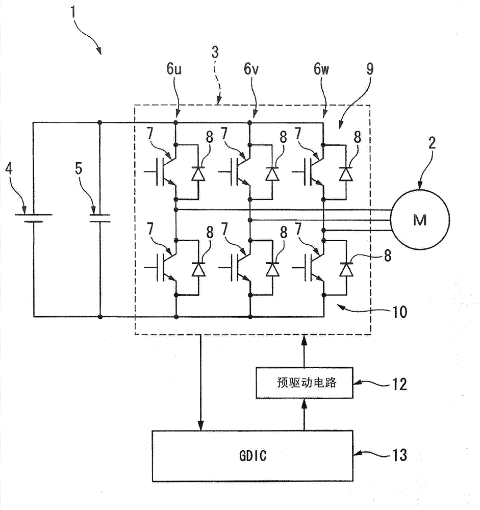
[0026] Next, the short-circuit protection method in one embodiment of the present invention will be described with reference to the drawings. figure 1 It shows a motor control circuit 1 that controls a motor generator 2 as a drive source installed in a vehicle such as a hybrid car together with an internal combustion engine. The motor generator 2 may be, for example, a three-phase brushless DC motor. This DC motor includes a rotor (not shown) having permanent magnets used in a magnetic field, and a stator (not shown) wound with three-phase coils that generate a rotating magnetic field for rotating the rotor. An inverter circuit 3 is connected to the motor generator 2. A high-voltage battery 4 is connected to the inverter circuit 3 as a DC power source, and a smoothing capacitor 5 is connected in parallel between the high-voltage battery 4 and the inverter circuit 3.

[0027] The inverter circuit 3 is a so-called PWM inverter that energizes each coil of the motor generator 2 by ...


PUM


Abstract

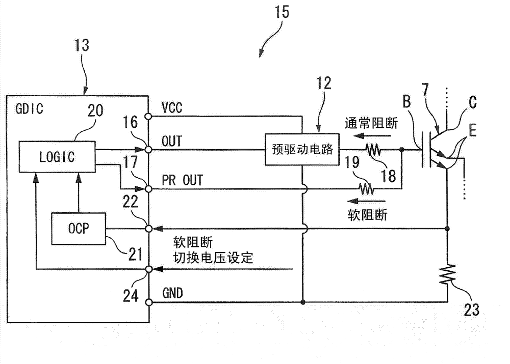
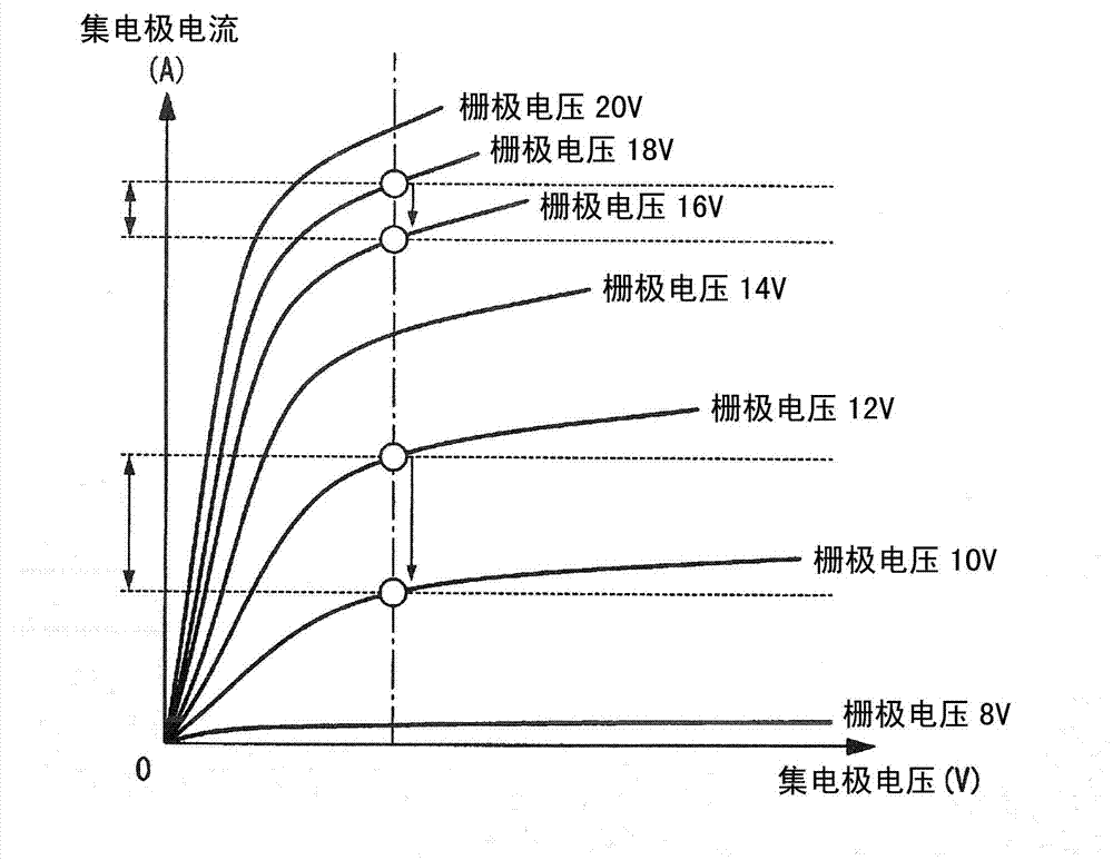
Disclosed is short-circuit protection method for circuits equipped with a plurality of power switching elements, wherein, in cases in which a short circuit has been detected in one power switching element by means of a detection means for detecting short circuits in the aforementioned power switching elements, a shutdown process is executed that shuts down the gates of the other power switching elements through which the short circuit current from the short circuit in the aforementioned one power switching element is passed; and moreover, while the shutdown process is being executed, the value of the gate resistance of the aforementioned other power switching elements is changed.

Description

Technical field [0001] The present invention relates to a short circuit protection method for power switching elements and the like. [0002] This application claims priority based on Japanese Patent Application No. 2010-093530 filed in Japan on April 14, 2010, and uses the content here. Background technique [0003] In a vehicle that is driven by a motor, such as an electric vehicle or a hybrid vehicle, an inverter in which power switching elements are connected to a bridge is used to perform motor control. For example, the following short-circuit protection method is known. When a short-circuit fault occurs in the power switching element of either the upper arm or the lower arm of the inverter, the power of the upper arm and the lower arm that does not have a short-circuit fault is blocked The gate of the switching element is controlled so that a large short-circuit current does not flow. [0004] Generally, when the response time of the power switching element is short, the curr...

Claims


Application Information

Patent Timeline
Patent Type & Authority Applications(China)
IPC IPC(8): H03K17/082H02M1/08H02M1/32
CPCH02M1/32H02M1/08H03K17/163H02H3/087H03K17/0828H03K17/168
Inventor 桥本纯一筱原贞夫
Owner HONDA MOTOR CO LTD
Learn More