Combined draining and saline controlling system for saline and alkaline land

A saline-alkali land and underground drainage technology, which is applied in soil drainage, construction, application, etc., can solve the problems of high project cost and large one-time investment, and achieve the effect of reducing the excavation area, facilitating construction, and promoting high-efficiency agricultural production

Active Publication Date: 2013-01-30
HOHAI UNIV
6 Cites 20 Cited by

AI-Extracted Technical Summary

Problems solved by technology

However, the underground pipe drainage technology generally uses local material pipes or plastic pipes, and the project...

Method used

(2) Straw replaces plastic dark pipe to reduce engineering investment on the one hand, can take materials on the spot on the other hand, has solved the unfavorable phenomenon that farmland rice and wheat straw has nowhere to lay for a long time, burns at will. Moreover, straw burial can increase soil fertility and ensure high agricultural production and income. It can be seen that the straw filling technology not only reduces the project investment, but also prevents environmental pollution and resource waste;
(4) Horizontal culvert drainage and vertical drainage are integrated into one, simple in structure, convenient in construction, and can be reused.
In summary, the saline-alkali land compound drainage and salt control system of the present invention integrates the horizontal and vertical drainage systems by designing a horizontal and vertical drainage system, and both achieves the goal of drainage and salt reduction The effect is to avoid the common problems of poor drainage, large excavation volume and easy collapse in the drainage process. The invention has simple structure and remarkable effect, is a salt washing system with practical application prospect, and has important popularization and application value. Its main advantages are as follows:
Please refer to Fig. 1, Fig. 2, shown in Fig. 3 and Fig. 4, a kind of saline-alkali land compound drainage salt control system of the present invention, comprises underground drainage ditch 1, water collection well 2, ground drainage open ditch 3, reservoir 4 , Control gate 5 and water pump in the ditch. The underground drainage ditches 1 are arranged in the farmland 13 in a criss-cross pattern. Wherein, the section of the underground drainage ditch 1 is a trapezoidal section. The underground drainage ditch 1 includes a soil backfill layer 7 and a straw filling layer 6 , and the soil backfill layer 7 is arranged above the straw filling layer 6 . Rice, wheat or corn stalks can generally be used for filling the lower part. Straw instead of plastic hidden pipes reduces the project investment on the one hand, and on the other hand, it can obtain local materials, which solves the unfavorable phenomenon that rice and wheat straws in the farmland have nowhere to be placed for a long time and are incinerated at will. Moreover, straw burial can increase soil fertility and ensure high agricultural production and income. It can be seen that the straw filling technology not only reduces the project investment, but also prevents environmental pollution and resource waste. The depth of the underground drainage ditch 1 is 1.2-1.5m, and the width of the bottom of the underground drainage ditch 1 is 0.3-0.5m. The underground drainage ditch 1 adopts a trapezoidal section and must be excavated in advance, and the excavation depth shall meet the requirements for controlling the groundwater level. The spacing of the underground drainage ditch 1 depends on the soil texture and the permeability coefficient. Generally, 12-15m for clay soil, 15-20m for loam soil, and 20-30m for sandy loam. The underground drainage ditch 1 will serve as the main drainage channel for groundwater, and the gradient of the underground ditch is similar to the ground slope along the ditch, so as not to excavate too deep. The straw covering thickness is equal to the width of the ditch bottom, which is 0.3-0.5m. The straw must be bundled into a column with a diameter of 0.3-0.5m before laying, and then the straw should be buried to the bottom of the ditch and compact...

Abstract

The invention discloses a combined draining and saline controlling system for a saline and alkaline land. The combined draining and saline controlling system comprises underground draining subdrains, surface draining open channels, intra-channel controlling gates, water collecting wells, water pumps and reservoirs, wherein the underground draining subdrains are arranged in a farmland in a staggered mode; the surface draining open channels are perpendicular to the underground draining subdrains; the water collecting wells are arranged at joints of the underground draining subdrains; the water pumps are arranged in the water collecting wells; the reservoirs are arranged at tail ends of the surface draining open channels; and the intra-channel controlling gates are arranged between the surface draining open channels and the reservoirs. According to the combined draining and saline controlling system, a horizontal draining system and a vertical draining system are integrated, so that draining and saline reducing effects are achieved, and the common problems that water is drained unsmoothly, the excavation area is large, collapse easily occurs and the like are solved.

Application Domain

Technology Topic

Image

  • Combined draining and saline controlling system for saline and alkaline land
  • Combined draining and saline controlling system for saline and alkaline land
  • Combined draining and saline controlling system for saline and alkaline land

Examples

  • Experimental program(1)

Example Embodiment

[0021] In the following, the present invention will be further clarified with reference to the accompanying drawings and specific embodiments. It should be understood that these embodiments are only used to illustrate the present invention and not to limit the scope of the present invention. After reading the present invention, those skilled in the art will understand various aspects of the present invention. Modifications in equivalent forms fall within the scope defined by the appended claims of this application.
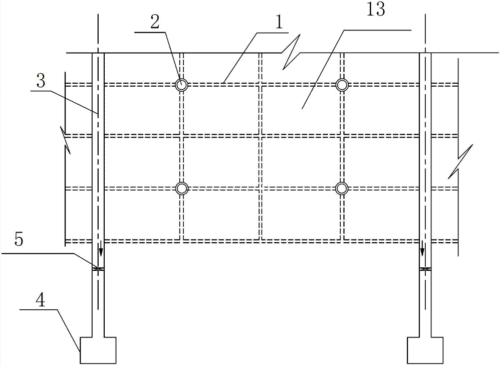
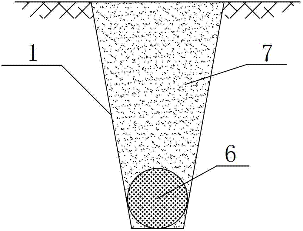
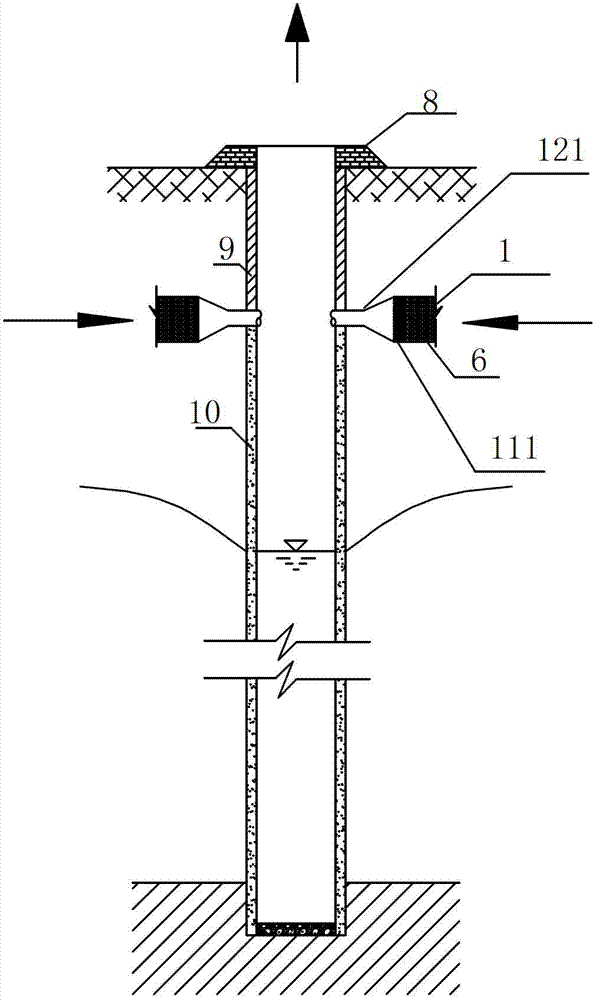
[0022] See figure 1 , figure 2 , image 3 with Figure 4 As shown, a compound drainage and salt control system for saline-alkali land of the present invention includes underground drainage ditch 1, water collection well 2, surface drainage open ditch 3, reservoir 4, control gate 5 in the ditch, and a water pump. Underground drainage ditches 1 are arranged crisscross each other in farmland 13. Among them, the section of the underground drainage ditch 1 is a trapezoidal section. The underground drainage ditch 1 includes a soil backfill layer 7 and a straw filling layer 6, and the soil backfill layer 7 is arranged above the straw filling layer 6. Generally, rice, wheat or corn stalks can be selected for the lower filling straw. Using straw instead of plastic concealed pipes on the one hand reduces the project investment, on the other hand, it can be used to obtain local materials, which solves the long-standing undesirable phenomenon that the rice and wheat straws have nowhere to be placed and burned at will. Moreover, landfill of straw can increase soil fertility and ensure high agricultural yield and income. It can be seen that the straw filling technology not only reduces the project investment, but also prevents environmental pollution and resource waste. The depth of the underground drainage ditch 1 is 1.2-1.5m, and the width of the bottom of the underground drainage ditch 1 is 0.3-0.5m. The underground drainage ditch 1 adopts a trapezoidal section and must be excavated in advance, and the excavation depth shall meet the requirements of controlling the groundwater level. The spacing of underground drainage ditch 1 depends on soil texture and permeability coefficient. Generally, 12-15m for clay, 15-20m for loam, and 20-30m for sandy loam. Underground drainage ditch 1 will be used as the main drainage channel for groundwater. The slope of the ditch is similar to the slope of the ground along the trench to avoid excessive excavation. The thickness of straw covering is equal to the width of the bottom of the trench, which is 0.3-0.5m. Before laying the straw, it must be bundled into a column with a diameter of 0.3-0.5m, and then the straw should be filled to the bottom of the ditch and compacted tightly. Finally, the soil is backfilled to the farming layer. Among them, the underground drainage ditches 1 that intersect with each other are perpendicular to each other, the layout is reasonable, and the drainage is even.
[0023] The surface drainage ditch 3 and the underground drainage ditch 1 are perpendicular to each other. The cross section of the ground drainage ditch 3 is a trapezoid cross section. The daily water level in the ditch is lower than the groundwater burial depth required by the farmland, and is generally 1.0-1.5m above the ground. The present invention is aimed at the demand for salt control, and the daily water level must be maintained at 2.2-2.6m. The drainage water level in the ditch depends on the water level in the drainage area of ​​the system. In the present invention, water storage ponds and dams are arranged at the end of each dragon ditch as the drainage area, and the self-draining method is adopted as the main drainage method. Therefore, the drainage level is determined according to the design flow of the drainage. A first filter screen 11 is provided at the junction of the underground drainage ditch 1 and the surface drainage ditch 3, and the first filter screen 11 is set at the junction of the first outlet pipe 12 and the underground drainage ditch 1 to filter the gravel and weeds in the water. . The underground drainage ditch 1 is connected to the first outlet pipe 12 leading to the surface drainage ditch 3, and the first outlet pipe 12 is a plastic reducing pipe. The pipe of the first outlet pipe 12 is wrapped or filled with an outer filter material to prevent soil particles from entering the underground drainage ditch 1 to prevent sedimentation and clogging of the concealed pipe, stabilize the surrounding soil, and improve the water seepage ability of the concealed pipe channel to improve the drainage function.
[0024] The collection well 2 is set at the intersection of the underground drainage ditch 1. The depth of the collection well 2 is 15-20m, the diameter of the wellhead of the collection well 2 is 0.5-0.8m, and the distance between adjacent collection wells 2 is 40-50m. The collection wells are arranged in a square shape. A well platform 8 is provided at the wellhead of the water collection well 2, and the wall of the water collection well 2 adopts a pipe string composed of a well wall tube 9 and a water filter tube 10, and is vertically installed in a well bore prepared in advance. The well wall pipe 9 is installed at the soil water-proof layer, and the filter pipe 10 is installed at the soil aquifer. The underground drainage ditch 1 is connected to the collection well 2 through the second outlet pipe 121. A second filter screen 111 is provided at the connection between the underground drainage ditch 1 and the collection well 2, and the second filter screen 111 is installed in the second outlet pipe 121 and the underground The junction of the drainage ditch 1 is used to filter the gravel and weeds in the water. The second outlet pipe 121 adopts a plastic reducing pipe. Clay balls are used to stop water at the junction of underground drainage ditch 1 and water collection well 2 to prevent leakage. The annular gap between the well pipe and the well bore is filled with sieved gravel or other artificial fillers to filter water and block sand. The bottom end of the collection well 2 is a sedimentation pipe, which is used to sediment the sediment flowing into the well.
[0025] The water pump is arranged in the water collection well 2. Among them, the water pump is a submersible pump. When washing salt in a large area, the submersible pump is used to pump the groundwater in the collection well 2 to the reservoir 4 to empty the storage capacity and reduce the groundwater level.
[0026] The reservoir 4 is set at the end of the open drainage ditch 3 on the ground. The reservoir 4 is excavated at the end of the farm ditch to accept the amount of water discharged from the drainage system. The reservoir 4 should be arranged at or near the lowest end of the drainage area to facilitate centralized drainage. When the drainage system drains the daily flow, its water level should not cause the drainage system to produce stagnant water to ensure normal drainage; when the system is washing salt in a large area or during the flood season, the storage pond and dam have sufficient storage capacity to hold the drainage system in time. The total amount of water.
[0027] An in-ditch control gate is arranged between the surface drainage ditch 3 and the reservoir 4. The control gate 5 in the ditch is a culvert gate. The control gate 5 in the ditch is arranged perpendicular to the center line of the ground drainage open ditch 3, and is set at the end of the ground drainage open ditch 3, using a culvert gate. The control gate is mainly used to control the water level in the ditch and prevent excessive loss of irrigation water.
[0028] Salt control method for compound drainage in saline-alkali land:
[0029] 1. When washing a large area of ​​salt, open the control gate 5 in the ditch, and use a submersible pump to pump the water in the reservoir 4 into the farmland 13. The water in the reservoir 4 is mainly composed of the groundwater and the groundwater extracted from the collection well 2. The composition of daily rainfall runoff. When washing salt, a large amount of fresh water or brackish water infiltrates the underground drainage ditch 1 from the surface of the soil and is discharged along the straw filling layer 6. Part of the water body is discharged into the surface drainage ditch 3 and then flows back to the reservoir 4, and the other part of the water body drains underground. The ditch 1 drains into the collection well 2. After the salt washing is over, the water in the collection well 2 is pumped back to the reservoir 4 with a submersible pump. The water in the reservoir 4 is recharged by ground fresh water and rainfall runoff or recharged by side seepage of the ditch, and its salinity will gradually decrease. By regularly washing a large area of ​​salt, salty groundwater can be gradually discharged, desalinated groundwater, and promote soil desalination.
[0030] 2. During daily irrigation, close the control gate 5 in the ditch, and use the submersible pump to irrigate the fresh or brackish water in the reservoir 4 into the farmland 13, and the irrigation water flows through the surface layer of the soil to infiltrate the planned soil wet layer and then partly flows Underground drainage ditch 1, this part of the return water will be discharged along the ditch 1 into the surface drainage ditch 3. Since the control gate 5 in the ditch is closed, the water level in the surface drainage ditch 3 is connected with the water level of the underground drainage ditch 1, which can reduce the leakage and loss of irrigation water and improve the utilization efficiency of irrigation water. Part of the remaining irrigation water will gradually flow into the collection well 2 along the underground drainage ditch 1. After the irrigation is completed, the control gate 5 in the ditch is opened, and the water in the open drainage ditch 3 on the ground is discharged into the reservoir 4.
[0031] In summary, the composite drainage and salt control system for saline-alkali soils of the present invention integrates both horizontal and vertical drainage systems by designing a horizontal and vertical drainage system, which not only achieves the effect of drainage and salt reduction, but also avoids In the drainage process, the common problems such as poor drainage, large excavation volume, and easy collapse are solved. The invention has a simple structure and significant effects, is a salt washing system with practical application prospects, and has important promotion and application value. The main advantages are as follows:
[0032] (1) The combined drainage method of horizontal ditch drainage and vertical well drainage can significantly reduce the groundwater level, reduce soil salinity, prevent secondary salinization, and promote efficient agricultural production;
[0033] (2) Straws instead of plastic concealed pipes reduce the project investment on the one hand, and on the other hand, they can obtain local materials, which solves the undesirable phenomenon of long-term farmland rice and wheat straws that have no place to be placed and burned at will. Moreover, landfill of straw can increase soil fertility and ensure high agricultural yield and income. It can be seen that the straw filling technology not only reduces the project investment, but also prevents environmental pollution and resource waste;
[0034] (3) Compared with traditional concealed pipe drainage, underground ditch drainage can effectively reduce the area of ​​ground excavation, increase the utilization rate of farmland, facilitate mechanical farming, and achieve the purpose of efficient use of agricultural land;
[0035] (4) The horizontal drainage and vertical drainage are integrated, the structure is simple, the construction is convenient, and it can be reused.

PUM

PropertyMeasurementUnit
Depth15.0 ~ 20.0m
tensileMPa
Particle sizePa
strength10

Description & Claims & Application Information

We can also present the details of the Description, Claims and Application information to help users get a comprehensive understanding of the technical details of the patent, such as background art, summary of invention, brief description of drawings, description of embodiments, and other original content. On the other hand, users can also determine the specific scope of protection of the technology through the list of claims; as well as understand the changes in the life cycle of the technology with the presentation of the patent timeline. Login to view more.

Similar technology patents

Classification and recommendation of technical efficacy words

  • Simple structure
  • Good effect

Microlithographic projection exposure apparatus

InactiveUS20050068499A1Simple structureReliable and low-maintenance operationProjectorsPhotomechanical exposure apparatusCamera lensPhysics
Owner:CARL ZEISS SMT GMBH

Hyperlipemia therapeutic agent

ActiveUS20050187292A1Good effectBiocideMetabolism disorderEPA - Eicosapentaenoic acidHyperlipidemia
Owner:KOWA CO LTD +1
Why Eureka
Try Eureka