Rotary hydraulic system of excavator and control method

A technology for hydraulic systems and excavators, applied in hydraulic systems, excavator slewing hydraulic systems and control fields, can solve the problems of reducing main pump power and energy waste, and achieve the effects of reducing displacement, avoiding energy waste, and reducing power

Active Publication Date: 2013-01-30
中外合资沃得重工(中国)有限公司
View PDF8 Cites 15 Cited by
  • Summary
  • Abstract
  • Description
  • Claims
  • Application Information

AI Technical Summary

Problems solved by technology

Existing medium and large excavators with electronic control systems are supplied with full-flow oil by the plunger pump when performing single-slewing operations. This method will cause energy waste due to large-flow overflow when the slewing starts
[0003] In recent years, users have increasingly increased requirements for the operating comfort and energy saving o

Method used


Image

  • Rotary hydraulic system of excavator and control method
  • Rotary hydraulic system of excavator and control method

Examples


Embodiment Construction

[0017] The present invention will be further described below in conjunction with the accompanying drawings and specific embodiments.

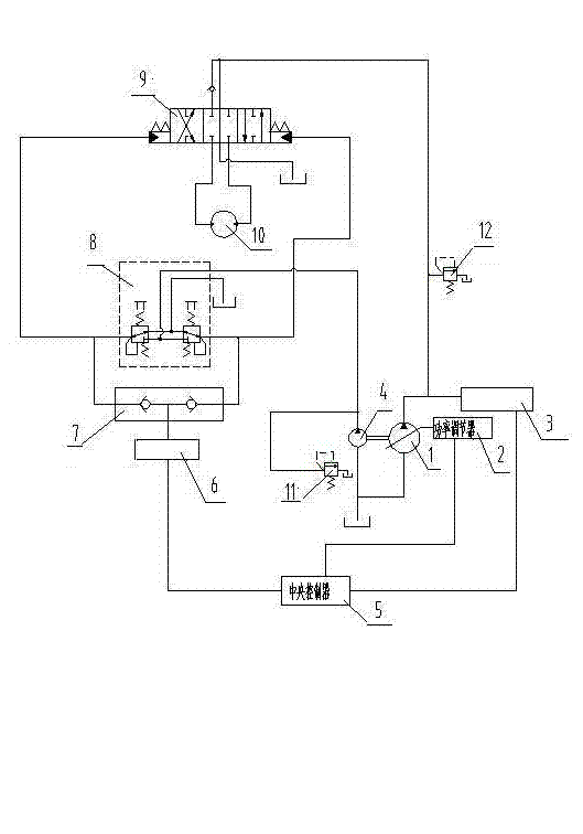
[0018] Such as figure 1 As shown, the slewing hydraulic system of the excavator includes a variable displacement plunger pump 1, an electronically controlled power regulator 2, a first pressure transmitter 3, a pilot pump 4, a central controller 5, a second pressure sensor 6, a logic shuttle valve 7, a pilot Valve 8, reversing valve 9, swing motor 10, pilot relief valve 11, main relief valve 12. The pilot pump 4, pilot valve 8, pilot relief valve 11, and logic shuttle valve 7 form a pilot oil circuit, the oil tank is connected to the pilot pump 4, the outlet of the pilot pump 4 is connected to the inlet of the pilot relief valve 11, and the pilot relief valve 11 outlet returns to the oil tank, the outlet of the pilot pump 4 is also connected with the pilot valve 8, the pilot valve 8 controls the reversing valve 9, the logic shuttle valve 7 is ...


PUM


Abstract

The invention discloses a rotary hydraulic system of an excavator and a control method. The rotary hydraulic system of the excavator comprises a variable displacement plunger pump, an electronic-control power regulator, a first pressure sensor, a pilot pump, a central control unit, a second pressure sensor, a logic shuttle valve, a pilot valve, a reversing valve, a rotary motor, a pilot overflow valve and a main overflow valve. The control method of the system comprises the following steps of presetting a set pressure value Pm and a pilot logic signal of the main overflow valve; reading a pilot signal; comparing the pilot signal with the pilot logic signal to judge whether single rotary action is carried out, if not, keeping the original power of a main pump, or else, entering the next step; reading a pressure value P of the main pump, judging whether the pressure value P is greater than or equal to the set pressure value Pm of the main overflow valve, if not, keeping the original power of the main pump, or else, entering the next step; and adjusting the power of the main pump and reducing the discharge capacity. During the single rotary action of the excavator, the rotary hydraulic system is used for adjusting the power of the main pump, so that the energy is saved by reducing the power under the premise of satisfying the normal operation.

Description

technical field [0001] The invention relates to a hydraulic system of an excavator, in particular to an excavator rotary hydraulic system and a control method, and belongs to the technical field of construction machinery equipment. Background technique [0002] An excavator is an earth-moving machine that uses the rotation of the platform and the cooperation of the boom, arm, and bucket to excavate or move soil or materials that are higher or lower than the bearing surface, and load them into transport vehicles or unload them to the stockyard. Existing medium and large excavators with electronic control systems are all supplied with full-flow oil by the plunger pump when performing single-slewing operations. This method will cause energy waste due to large-flow overflow when the slewing starts. [0003] In recent years, users have increasingly increased requirements for the operating comfort and energy saving of construction machinery, especially excavators, and slewing is ...

Claims


Application Information

Patent Timeline
IPC IPC(8): E02F9/20E02F9/22
Inventor 牛选平高剑英赵健雄孙永建
Owner 中外合资沃得重工(中国)有限公司
Why Eureka
Try Eureka