H-type rotary joint
A technology of rotary joint and main body, applied in the direction of pipe/pipe joint/pipe fitting, adjustable connection, mechanical equipment, etc., can solve the problems of short service life, poor sealing, heavy weight, etc., to ensure reliability, low friction, light weight effect
- Summary
- Abstract
- Description
- Claims
- Application Information
AI Technical Summary
Problems solved by technology
Method used
Image

Examples
Embodiment 1
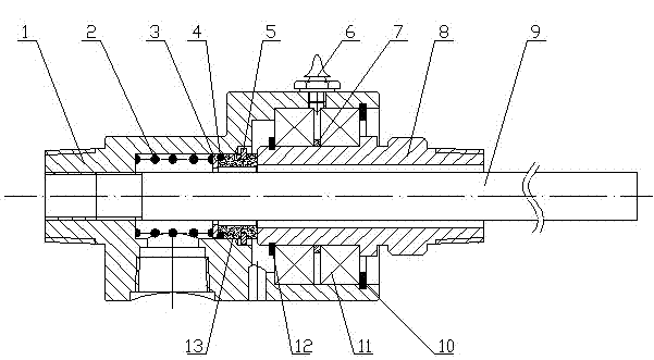
[0011] An H-shaped rotary joint, comprising a joint main body 1, a spacer ring 7, a hollow shaft 8, an inner water pipe 9, a circlip 10 for holes, a bearing 11, and a circlip 12 for a shaft. The inner water pipe 9 is arranged on the joint In the main body 1, the joint also includes a spring compensating assembly and a sealing assembly connected to each other. The spring compensating assembly and the sealing assembly are arranged at the rear of the hollow shaft 8. The spring compensating device includes a spring 2, a gasket 3 and an O-ring 4, one end of the spring 2 is set in the inner hole of the joint body 1, and the other end is connected to the gasket 3 and the O-ring 4 in turn; the sealing assembly includes a silicon carbide seal 13 and The cylindrical pin 5 is arranged in the hole on the outer surface of the silicon carbide seal 13. The joint main body 1 is also provided with an oil cup 6 and an observation hole. The oil outlet of the oil cup 6 is connected to the bearing ...
Embodiment 2
[0013] An H-type rotary joint, including a joint body 1, a spacer ring 7, a hollow shaft 8, a circlip 10 for a hole, a bearing 11, and a circlip 12 for a shaft, and the joint also includes interconnected spring compensation components and The sealing assembly, the spring compensation assembly and the sealing assembly are arranged at the rear of the hollow shaft 8, the spring compensation device includes a spring 2, a gasket 3 and an O-ring 4, and one end of the spring 2 is arranged at the joint In the inner hole of the main body 1, the other end is connected to the gasket 3 and the O-ring 4 in turn; the sealing assembly includes a silicon carbide seal 13 and a cylindrical pin 5, and the cylindrical pin 5 is arranged on the outer surface of the silicon carbide seal 13 In the hole, the joint main body 1 is also provided with an oil cup 6 and an observation hole, and the oil outlet of the oil cup 6 communicates with the bearing 11 . Any one of the water inlet and outlet on the jo...
PUM
 Abstract
Description
Claims
Application Information
 - R&D
- Intellectual Property
- Life Sciences
- Materials
- Tech Scout
- Unparalleled Data Quality
- Higher Quality Content
- 60% Fewer Hallucinations
Browse by: Latest US Patents, China's latest patents, Technical Efficacy Thesaurus, Application Domain, Technology Topic, Popular Technical Reports.
© 2025 PatSnap. All rights reserved.Legal|Privacy policy|Modern Slavery Act Transparency Statement|Sitemap|About US| Contact US: help@patsnap.com