
Core three-dimensional multi-parameter measuring instrument based on visual observation of crack

A multi-parameter, measuring instrument technology, applied in the direction of measuring devices, scientific instruments, suspension and porous material analysis, etc., can solve the problems of inability to complete rock anisotropy, inability to complete rock physical parameters at the same time, single function, etc.

Inactive Publication Date: 2013-01-30
CHINA UNIV OF PETROLEUM (EAST CHINA)
View PDF4 Cites 26 Cited by
  • Summary
  • Abstract
  • Description
  • Claims
  • Application Information

AI Technical Summary

Problems solved by technology

However, the existing core fracture visualization device has a single function, can only be used to observe fractures, and cannot simultaneously complete the measurement of various petrophysical parameters such as porosity, permeability, resistivity, and sound waves; The plunger-like core is the experimental object, and only the fractures on the two end faces of the plunger core can be observed, and the research on the anisotropy of the rock cannot be completed. An experimental device for measuring anisotropic multi-parameters is a necessary way to conduct experimental research on cracks at present

Method used


Image

  • Core three-dimensional multi-parameter measuring instrument based on visual observation of crack
  • Core three-dimensional multi-parameter measuring instrument based on visual observation of crack
  • Core three-dimensional multi-parameter measuring instrument based on visual observation of crack

Examples


Embodiment 1

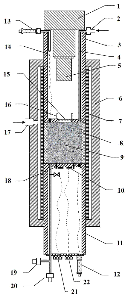
[0024] Example 1: Such as figure 1 As shown, the core holder includes a kettle body 6. The lower end of the kettle body 6 is equipped with a common lower plunger 11, and a rubber sleeve 8 is arranged above the common lower plunger. The upper end of the core 9 corresponds to the upper end of the square core 9 and the upper end of the rubber sleeve 8 with a visualization plunger 3 installed. In this embodiment, the visualization plunger 3 includes a camera 1 installed on the upper end of the visualization plunger cylindrical barrel and extending into the visualization plunger barrel. The camera 1 is equipped with a zoom lens 5, and the zoom lens 5 is There is a glass observation window 15 for observation on the lower end surface of the corresponding visualization plunger 3, and the two sides of the glass observation window 15 correspond to the inner surface of the bottom end of the visualization plunger cylinder with visible light sources 16 for supplying visible light. The outer...

Embodiment 2

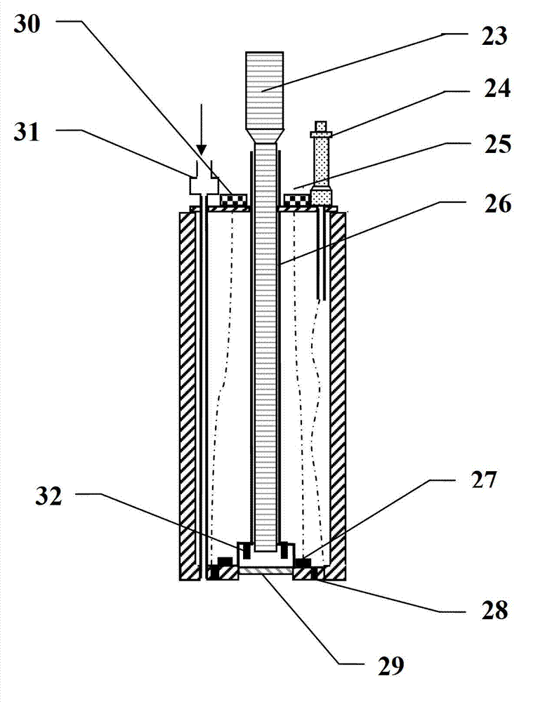
[0029] Example 2: figure 2 Shown is the schematic diagram of the electroacoustic plunger section, which is needed when measuring the electroacoustic parameters of the rock by the instrument figure 2 Electroacoustic plunger replacement shown in figure 1 The visualization plunger 3, the kettle body and the lower plunger part and figure 1 The same as shown in. In this embodiment, the electroacoustic plunger includes an electroacoustic plunger endoscope 23 for observing changes in the end face of the core, and the exterior of the electroacoustic plunger endoscope 23 is used to fix the position of the endoscope The hollow annular electroacoustic plunger connecting rod 26 is equipped with a visible light source 32 for providing visible light at the lower end of the electroacoustic plunger connecting rod. A glass observation window 29 is directly below the visible light source 32. The glass observation Outside the window 29 is an electrode ring 28 embedded in the bottom end surface o...

Embodiment 3

[0034] Example 3: image 3 Shown is a schematic diagram of the porosity and permeability plunger profile. The porosity and permeability plunger is used to measure the porosity and permeability parameters of the rock sample. image 3 Porosity plunger replacement shown in figure 1 In the visualization plunger, the rest remains unchanged. In this embodiment, there is an endoscope 33 in the middle of the porosity plunger for observing the change of the end face of the core, and outside the endoscope is a ring-shaped porosity plunger connecting rod 35 for fixing the endoscope. The lower end of the permeable plunger rod 35 is equipped with a visible light source 36 for providing light, and a transparent glass observation window 37 is installed directly below the visible light source 36 and the endoscope 33. The glass observation The window 37 is inlaid in the center of the lower end surface of the porosity plunger. The outer side of the endoscope 33 corresponds to the outer edge of th...


PUM

PropertyMeasurementUnit
Outer diameteraaaaaaaaaa

Abstract

The invention provides a core three-dimensional multi-parameter measuring instrument based on visual observation of crack. The instrument comprises a controller and a core holder. The controller is used for sending and receiving signal; and measurement of all core parameters is finished in the core holder. The instrument uses nosean core as a main subject, and is provided with upper plungers with three different functions comprising a visualization plunger, an electroacoustic plunger and a porosity permeability plunger, and a public lower plunger. For experiments, nosean core is placed into the holder which is loaded with plungers at both ends, and parameters of the system are set, so that the instrument can automatically complete the corresponding parameter tests. Under conditions of heating and pressurization, the visualization plunger is used to realize real-time observation on crack changes and measurement of crack width through an internally configured camera; the electro-acoustic plunger and the porosity permeability plunger can measure parameters of core, such as porosity, permeability velocity, wave velocity and resistivity, and observe a displacement process and changes of core cracks; and measurement of parameters at three directions X,Y and Z of the core can be realized by changing loading direction of nosean core.

Description

Technical field: [0001] The invention relates to an automatic parameter measurement device for visualizing core fractures, that is, real-time recording of state changes of fractures in various directions of the core during an experiment process, and finally analyzing the fractures in two ways of image and numerical value. In particular, a measuring instrument that can measure the core XYZ three directions while observing the core fracture changes and widths. Background technique: [0002] Fractures provide reservoir space and oil and gas migration channels for the reservoir, but they also cause the heterogeneity of the internal flow of the reservoir and the separation of the reservoir. The study of reservoir fractures is a difficult point in oil and gas exploration, and core analysis is a necessary means to study fractures. The research on rock cracks requires efficient experimental devices to carry out basic experimental research. The existing core crack visualization device i...

Claims


Application Information

Patent Timeline
IPC IPC(8): G01N15/08G01N27/02G01N29/07
Inventor 孙建孟陈一健董旭张丽艳李召成
Owner CHINA UNIV OF PETROLEUM (EAST CHINA)
Learn More