Reactive compensation discharge device

A discharge device and compensation capacitor technology, applied in reactive power compensation, circuit devices, reactive power adjustment/elimination/compensation, etc., can solve problems that are difficult to implement, have little effect on re-ignition rate, and are difficult to apply in practice. The effect of eliminating reignition, omitting aging experiments, and improving reliability and safety

Inactive Publication Date: 2013-01-30
合肥溢鑫电力科技有限公司
View PDF5 Cites 2 Cited by
  • Summary
  • Abstract
  • Description
  • Claims
  • Application Information

AI Technical Summary

Problems solved by technology

[0005] 2. Technical improvements in mechanical structure and manufacturing process have little effect in reducing the reburning rate
[0008] ① Thyristor current zero-crossing and equipotential switching are limited by the development of power electronics. It is difficult to apply in practice, the cost is very high, the cost of maintenance is extremely high, and the reliability is poor. Currently, it can only be applied in low-voltage systems.
[0009] ② Vacuum circuit breaker current zero-crossing and equipotential switching (phase-controlled vacuum circuit breaker), due to the cost of thyristor current zero-crossing and equipotential switching, high maintenance costs, and poor reliability, some researchers use single-phase vacuum circuit breakers , the opening and closing time of each single-phase vacuum circuit breaker is controlled by a microcomputer, which is theoretically feasible and difficult to realize in practice, because the operating time of the vacuum circuit breaker’s operating mechanism is a large discrete time value interval, and the current cannot cross zero. And equipotential switching, still can not really reduce the re-ignition rate, this method has not yet been practically applied
That is to say, technical improvements in mechanical structure and manufacturing process have become powerless, with little effect, and cannot prevent the vacuum circuit breaker from restarting.

Method used


Image

  • Reactive compensation discharge device
  • Reactive compensation discharge device
  • Reactive compensation discharge device

Examples


Embodiment 1

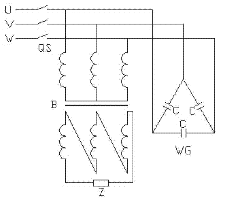
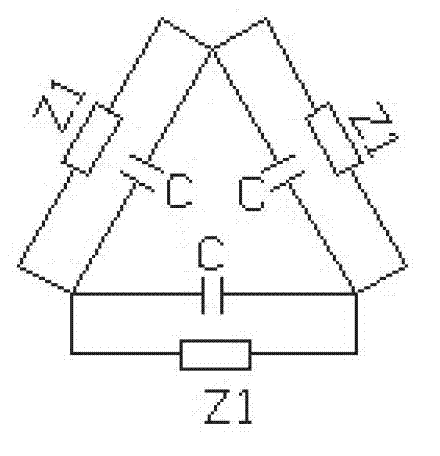
[0026] Such as Figure 4 In figure a, the 35kV reactive power compensation device is 12000kVar, the capacitor bank △ connection mode, the reactive power compensation discharge device transformer primary winding △ connection mode, the reactive power compensation discharge device transformer capacity is 6kVA, and the reactive power compensation discharge device transformer ratio is 150 : 1. The impedance of the secondary winding of the secondary winding of the reactive power compensation discharge device connected in parallel with the delta is a resistance, and its value is 1 ohm.

Embodiment 2

[0028] Such as Figure 4 In figure d, the 35kV reactive power compensation device is 9000kVar, the capacitor bank is Y connection mode, the primary winding of the transformer of the reactive power compensation discharge device is Y connection mode, the transformer capacity of the reactive power compensation discharge device is 3kVA, and the transformer ratio of the reactive power compensation discharge device is 90:1, the impedance of the secondary winding of the reactive power compensation discharge device connected in triangular parallel connection is resistance, and its value is 1.5 ohms.

Embodiment 3

[0030] Such as Figure 4 In the diagram e, the 10kV reactive power compensation device is 3000kVar, the capacitor bank is Y connection, the primary winding of the transformer of the reactive power compensation discharge device is Y connection, the neutral point of the transformer primary winding of the reactive power compensation discharge device is connected to the neutral point of the reactive power compensation capacitor bank The point-to-phase connection, the transformer capacity of the reactive power compensation discharge device is 3kVA, the transformer transformation ratio of the reactive power compensation discharge device transformer is 25:1, and the impedance of the secondary winding of the reactive power compensation discharge device connected in triangular parallel connection is resistance, and its value is 0.5 ohms .

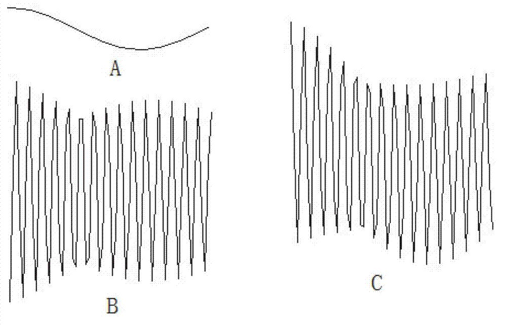
[0031] Principle analysis:

[0032] The charge stored in the reactive power compensation capacitor is the real culprit of the switch reignition

...


PUM


Abstract

The invention discloses a reactive compensation discharge device, which is characterized in that a primary-side three-phase winding of a three-phase transformer is in Delta-type connection or Y-shaped connection; the primary-side three-phase input end of the three-phase transformer is connected with the three-phase input end of a reactive compensation capacitor group in parallel; a secondary-side winding of the three-phase transformer is set to an open-delta connection mode, and impedance is accessed to the open-delta shape; and after a circuit breaker removes the reactive compensation capacitor group from the system, the interphase equivalent impedance and the reactive compensation interphone capacitance of the reactive compensation discharge device in the reactive compensation capacitor group form a discharging circuit for discharging. After the circuit breaker powers off the reactive compensation capacitor group, the reactive compensation discharge device discharges rapidly to the reactive compensation capacitor group, so that the voltage pressure of an on-off cut is smaller than the insulation intensity, and therefore the reignition of the reactive compensation capacitor group which is powered off by the circuit breaker is eliminated.

Description

technical field [0001] The invention relates to a reactive power compensation device for electric power. Background technique [0002] 1. Re-ignition of reactive power compensation vacuum circuit breaker is a worldwide problem [0003] Reactive power compensation cannot be overcompensated, so with the change of system operation mode, frequent switching of reactive power compensation capacitors, and the switching circuit breaker of reactive power compensation capacitors require no restrike. Vacuum circuit breakers have the advantages of small size, good arc extinguishing performance, long life, small maintenance, safe use, etc., and are widely used in medium voltage systems and power distribution networks. Especially because of its characteristics of being suitable for frequent operation, vacuum circuit breakers are basically used to switch reactive power compensation capacitor banks in parallel reactive power compensation capacitor compensation devices. [0004] In the pro...

Claims


Application Information

Patent Timeline
Patent Type & Authority Applications(China)
IPC IPC(8): H02H9/04H02J3/18
CPCY02E40/30
Inventor 张安斌
Owner 合肥溢鑫电力科技有限公司
Why Eureka
Try Eureka