Efficient insulation DC (direct-current) converter system in photovoltaic power generation system

A photovoltaic power generation system, a technology of isolating DC, applied in the direction of photovoltaic power generation, DC power input conversion to DC power output, adjustment of electrical variables, etc. Conversion efficiency, ensuring safety and reliability, and achieving the effect of power output

Inactive Publication Date: 2013-01-30
NANJING UNIV OF AERONAUTICS & ASTRONAUTICS
View PDF3 Cites 21 Cited by
  • Summary
  • Abstract
  • Description
  • Claims
  • Application Information

AI Technical Summary

Problems solved by technology

Since the full-bridge DC converter adopts phase-shift control to realize soft switching and works in an unregulated voltage state, the efficiency of the full-bridge DC converter is very high, but all power must be transmitted through the two-stage converter, which increases the system Power loss, and secondly, the output power of the photovoltaic string and the working efficiency of the Boost converter are not coordinated, which affects the power conversion efficiency of the entire system
[0004] Some scholars have proposed a power compensation method for improving the efficiency of photovoltaic grid-connected power generation systems using DC-DC series DC-AC power architecture in the full input voltage range: that is, using a controlled voltage source connected in series with photovoltaic strings to Compensate the difference between the output voltage of the photovoltaic string and the DC bus voltage, but this method has high requirements on the output voltage of the photovoltaic string, and requires the power compensator to be isolated, but the entire system has not yet achieved isolation, and there is leakage current, which has certain security risks

Method used


Image

  • Efficient insulation DC (direct-current) converter system in photovoltaic power generation system
  • Efficient insulation DC (direct-current) converter system in photovoltaic power generation system
  • Efficient insulation DC (direct-current) converter system in photovoltaic power generation system

Examples


specific example

[0032] A specific example of the present invention is as follows:

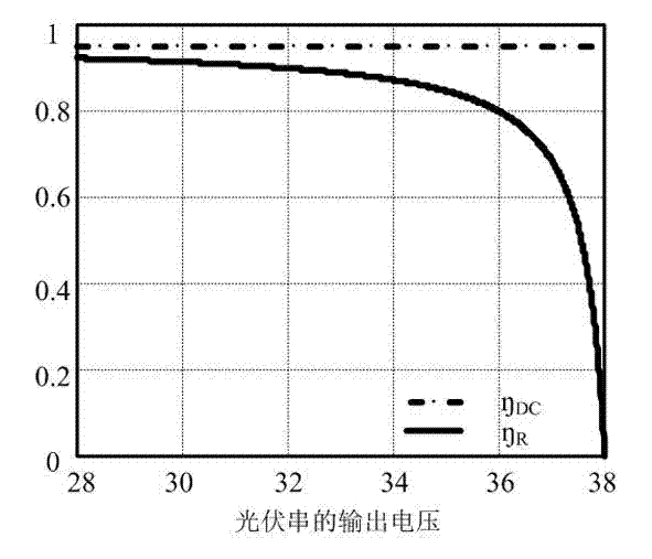
[0033] Solar photovoltaic cell input DC voltage: V PV =30~38 V ;

[0034] Output DC bus voltage: V o =380 V ;Output Power: P o =1kW;

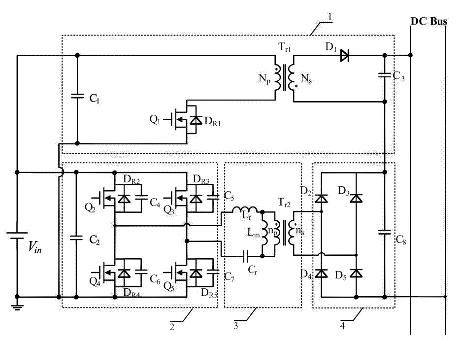
[0035] The DC transformer DCX is the switching frequency of the full-bridge LLC converter 2: f s =120kHz; resonant frequency: f r =120kHz; resonant inductance: L r =1.13uH; resonant capacitor: C r =1uF; excitation inductance: L m =7.78uH; second isolation transformer T r2 Ratio of primary and secondary sides: 1:10; switching tube Q 2 , Q 3 , Q 4 , Q 5 : IPP030N10N3G;

[0036] DC transformer DCX output current: I o_LLC =2.6 A ;rectifier diode D R5 , D R6 , D R7 , D R8 : IDT10S60C.

[0037] The power compensator PVR is the flyback circuit 1 switching frequency: f s =50kHz; the first isolation transformer Tr 1 Ratio of primary and secondary sides: 1:1; switching tube Q 1 : IPP200N25N3G; inductance: L =163uH; Freewheeling diode D 1...


PUM


Abstract

The invention discloses an efficient insulation DC (direct-current) converter system in a photovoltaic power generation system. The DC converter enables large part of power to be transmitted to a busbar voltage through an efficient direct-current transformer (DCX), and small part of power is transmitted through a power compensation device (PVR), namely the output voltage of the power compensation device is the difference value of the voltage of a voltage compensation busbar of a controlled voltage source and the DSC output voltage; when the input voltage is higher, the power transmitted through the PVR is higher, and the system efficiency is low relatively, reversely, most part of power is transmitted through the DCX, and the system efficiency is higher relatively; the DCX is selected from an insulation-type converter without regulating the voltage, which plays effects of voltage conversion and electric insulation; the PVR is selected from the insulation-type converter which operates between two kinds of operation modes including steady voltage and MPPT (maximum power point tracking); and when the maximal output power of a solar battery is greater than the power required by load, the converter operates under the steady voltage mode, and reversely, the converter operates under the MPPT mode.

Description

technical field [0001] The invention relates to a system structure of a high-efficiency isolated DC converter applied to a photovoltaic power generation system, and belongs to the field of new energy power supply systems. Background technique [0002] The environmental problems caused by the use of fossil energy worldwide and the depletion of traditional energy have made solar energy an attractive alternative energy source in this century, but it also faces the problem of low energy conversion efficiency of photovoltaic panels. Overall efficiency is an open question. The traditional high-frequency isolated photovoltaic grid-connected system has complicated system conversion links, which affects the system efficiency, and there is a problem that the working characteristics of the DC converter and the output power characteristics of the photovoltaic string are not well complemented and integrated. [0003] Commonly used DC converters include single-stage and two-stage power g...

Claims


Application Information

Patent Timeline
Patent Type & Authority Applications(China)
IPC IPC(8): H02M3/338
CPCY02E10/56
Inventor 孔月萍金科
Owner NANJING UNIV OF AERONAUTICS & ASTRONAUTICS
Why Eureka
Try Eureka