Universal type pitch circle positioning gear mill inner hole device
A technology for locating gears and grinding inner holes, which is used in grinding machines, grinding workpiece supports, grinding/polishing equipment, etc., can solve the problems of low clamping efficiency, wear failure, and low precision, and achieve high clamping efficiency and precision. Improve and ensure the effect of stability
- Summary
- Abstract
- Description
- Claims
- Application Information
AI Technical Summary
Problems solved by technology
Method used
Image

Examples
Embodiment Construction
[0020] The present invention will be further described below in conjunction with the examples, but not as a limitation of the present invention.
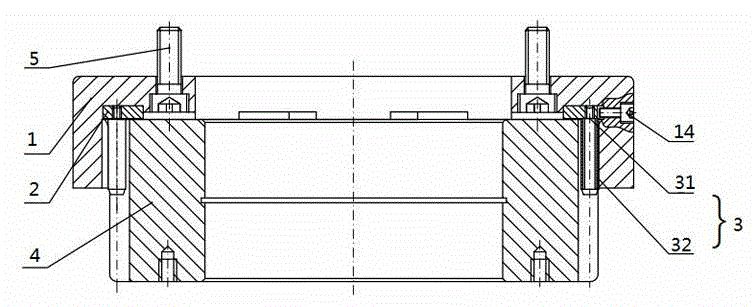
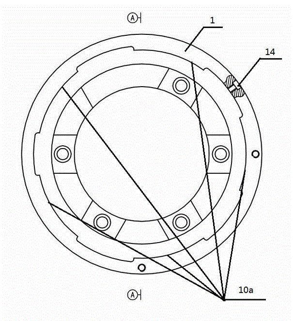
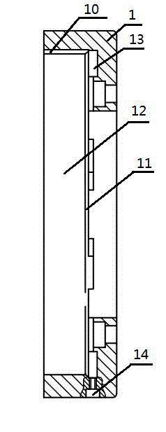
[0021] See Figure 1 to Figure 4 , a general-purpose pitch circle positioning gear grinding inner hole device, including a pitch circle clamp body 1, a roller positioning ring 2 and a roller 3, the pitch circle clamp body 1 inner wall 10 and the bottom surface 11 form a cavity 12 for accommodating the gear 4, and the inner wall 10 It includes five curved surfaces 10a, the trajectory of the curved surfaces 10a is an Archimedes spiral, and the inner wall 10 of the pitch circle clamp body is provided with limit screws 14 . A positioning groove 3 is provided at the bottom of the section round clip body 1, and a limit protrusion 20 is provided on the outer edge of the roller positioning ring 2, and the roller positioning ring 2 can rotate freely in the positioning groove 13, and the limit screw 14 and the limit protrusion 20 Cooperate t...
PUM
 Abstract
Description
Claims
Application Information
 - Generate Ideas
- Intellectual Property
- Life Sciences
- Materials
- Tech Scout
- Unparalleled Data Quality
- Higher Quality Content
- 60% Fewer Hallucinations
Browse by: Latest US Patents, China's latest patents, Technical Efficacy Thesaurus, Application Domain, Technology Topic, Popular Technical Reports.
© 2025 PatSnap. All rights reserved.Legal|Privacy policy|Modern Slavery Act Transparency Statement|Sitemap|About US| Contact US: help@patsnap.com