End face polishing and beveling machine of optical element

A technology of optical components and chamfering machines, applied to machine tools, grinding/polishing equipment, grinding machines, etc. suitable for grinding the edge of workpieces, it can solve the problems of not being able to polish at the same time, achieve good operability, improve efficiency and precision , highly controllable effect

Inactive Publication Date: 2013-02-06
XIAMEN UNIV
View PDF9 Cites 12 Cited by
  • Summary
  • Abstract
  • Description
  • Claims
  • Application Information

AI Technical Summary

Problems solved by technology

However, it is limited to cylindrical blan

Method used


Image

  • End face polishing and beveling machine of optical element
  • End face polishing and beveling machine of optical element
  • End face polishing and beveling machine of optical element

Examples


Embodiment Construction

[0027] The following embodiments will further illustrate the present invention in conjunction with the accompanying drawings.

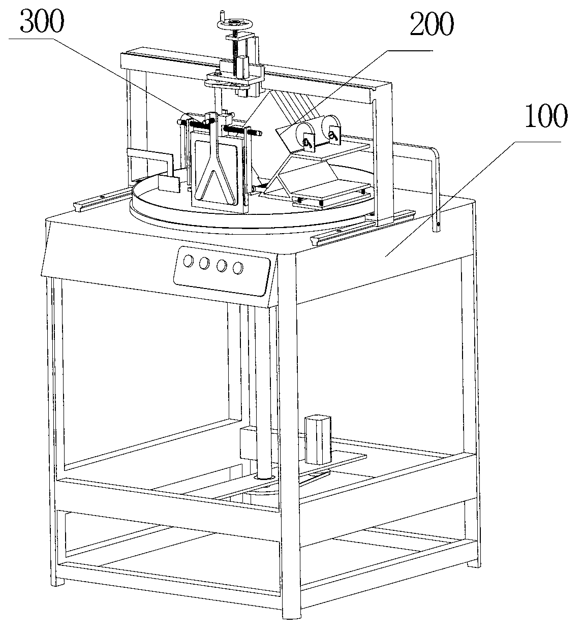
[0028] see figure 1 , the embodiment of the present invention consists of three major parts, namely the main body of the machine tool 100 , the polishing device 200 and the beveling device 300 .

[0029] see Figure 5 The main body of the machine tool is provided with a frame seat 23, a guide rail 24, a limiting arm 25, a gantry arm 26, a gantry arm slider 27, a grinding disc 28, a guide rail slider 29, a deflector 30, a current limiting ring 31, an operation panel 32, a motor 33 and belt wheel pair 34. Guide rail 24, limiting arm 25 are fixed on the frame seat 23 by screws, guide rail slider 29 and guide rail 24 form guide rail pair, gantry arm 26 is fixed on the guide rail slider 29, gantry arm slider 27 and gantry arm 26 form guide rail pair. The pulley pair 34 is connected with the grinding disc 28 and the motor 33 . The restrictor ring 31 is ...


PUM


Abstract

The invention relates to an end face polishing and beveling machine of an optical element, relating to an end face polishing and beveling machine, which is simple in structure and is capable of obviously improving the work efficiency. The end face polishing and beveling machine is provided with a machine tool main body, a polishing device and a beveling device; the machine tool main body is provided with a frame seat, a guide rail, a guide rail sliding block, a limit arm, a gantry arm, a gantry arm sliding block, a first electric motor, a first belt wheel pair, a grinding disc, a guide plate, a flow-limiting ring and an operation panel; the polishing device is provided with a supporting rack, a hand wheel, a lifting screw rod, a main shaft, a main screw rod, side screw rods, an end face clamping plate, side clamping plates, a second belt wheel pair and a second electric motor; and the beveling device is provided with a bottom board, a spring, a workpiece rack, a pawl and ratchet wheel mechanism, an eccentric wheel, side pressure plates and a top pressure plate.

Description

technical field [0001] The invention relates to an end face polishing and chamfering machine, in particular to an end face polishing and chamfering machine for an optical element after ultra-precision grinding. Background technique [0002] In recent years, high-precision optical components have been widely used in many fields such as laser nuclear fusion, aviation, spaceflight, space exploration and military observation, and the requirements for both quality and quantity are increasing day by day, which will exceed the capabilities of traditional optical manufacturing industries. Therefore, how to improve the surface quality and production efficiency of optical components has become a thorny problem. [0003] The processing of high-precision optical components is generally divided into two processes: grinding and polishing. Grinding comes first, followed by polishing. End face polishing and chamfering is a small process between grinding and polishing. The traditional end ...

Claims


Application Information

Patent Timeline
IPC IPC(8): B24B9/14
Inventor 郭隐彪林晓辉白志扬吴沿鹏
Owner XIAMEN UNIV
Why Eureka
Try Eureka