Method for manufacturing crude melt of glass raw materials and method for manufacturing optical glass

A technology of glass raw materials and manufacturing methods, applied in glass manufacturing equipment, manufacturing tools, glass furnace equipment, etc., can solve problems such as optical glass coloring

Inactive Publication Date: 2013-02-06
HOYA CORP
View PDF5 Cites 2 Cited by
  • Summary
  • Abstract
  • Description
  • Claims
  • Application Information

AI Technical Summary

Problems solved by technology

Also, several of these metals are reduced when heated at higher temperatures, and as a result, optical glasses are sometimes colored

Method used


Image

  • Method for manufacturing crude melt of glass raw materials and method for manufacturing optical glass
  • Method for manufacturing crude melt of glass raw materials and method for manufacturing optical glass
  • Method for manufacturing crude melt of glass raw materials and method for manufacturing optical glass

Examples


Embodiment A1

[0089] -Raw material melting furnace-

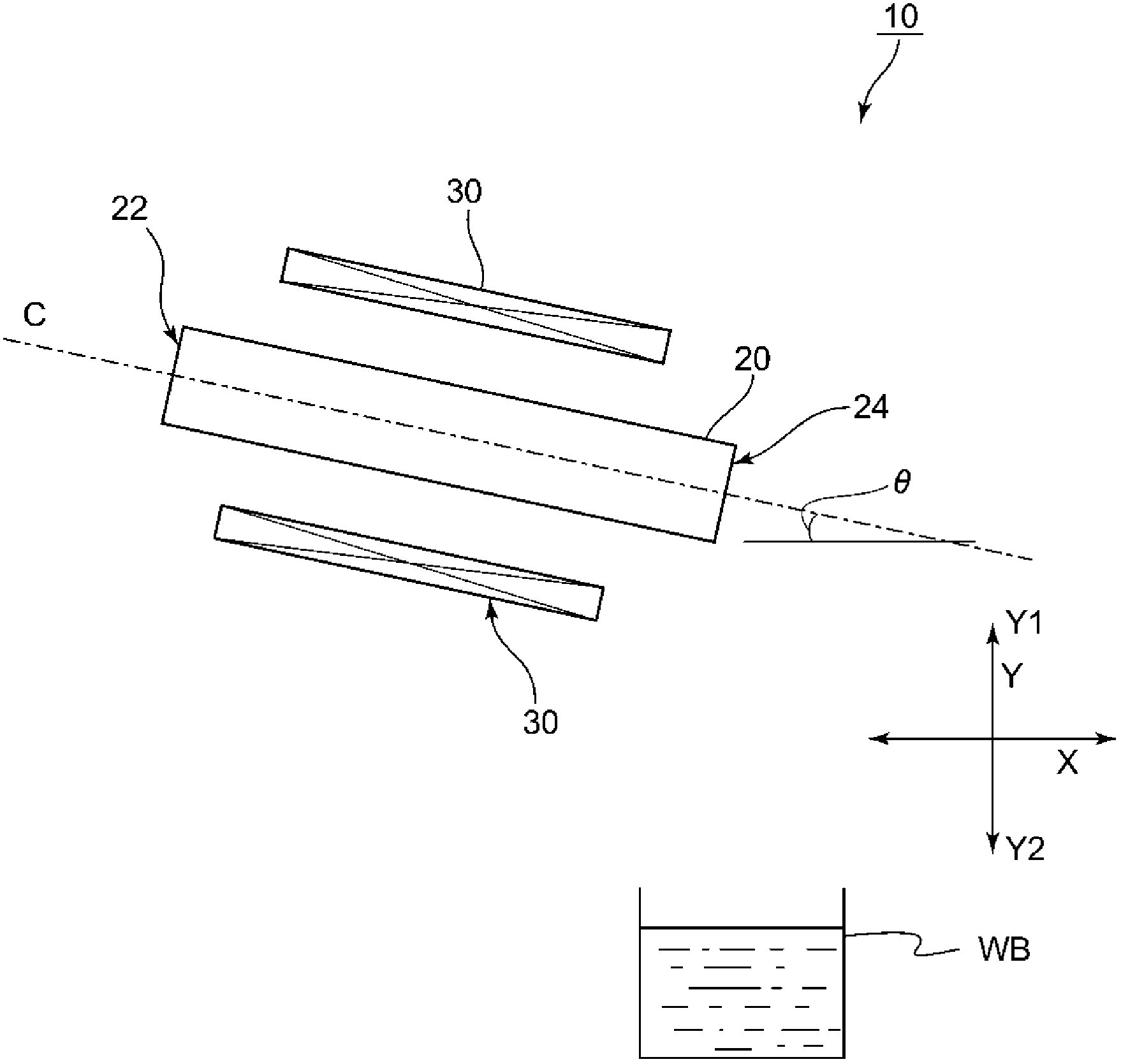
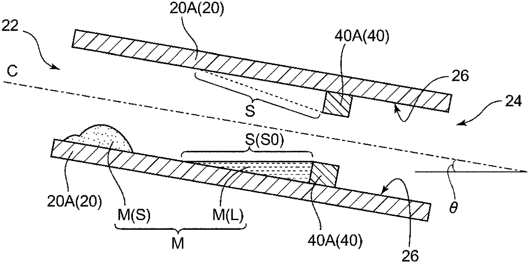
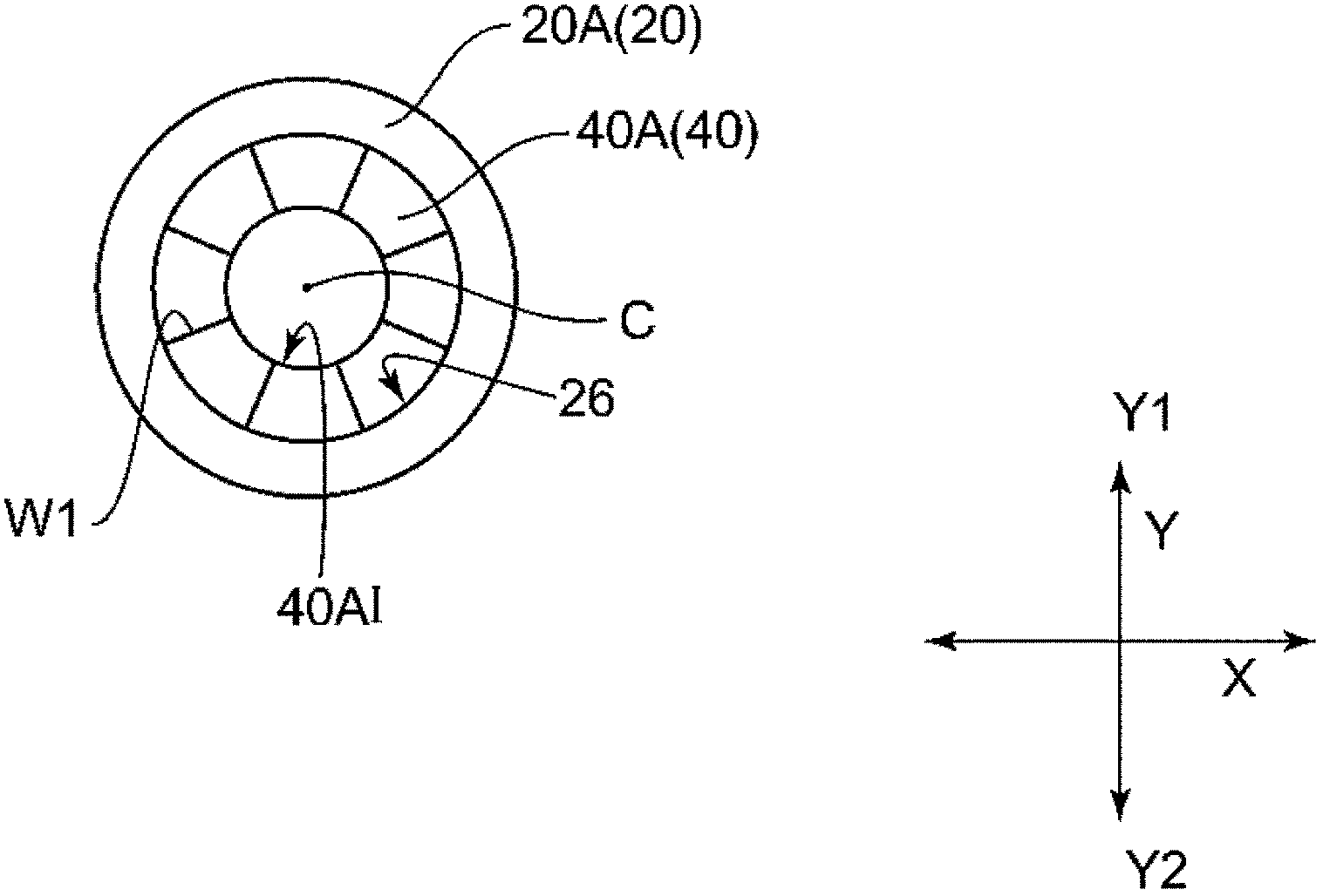
[0090] As a raw material melting furnace 10, a cylindrical tube 20 is used image 3 structure shown. All the constituent materials of the cylindrical tube 20B and the components disposed therein are made of quartz glass. Here, the dimensions and shape of the cylindrical tube 20B are: length 100 cm, outer diameter 10 cm, and inner diameter 8 cm, and the stagnation part forming member 40B is a ring-shaped member with a thickness of 5 cm, an outer diameter of 8 cm, and an inner diameter of 6 cm. After eighth equal parts, the shape is trimmed appropriately for easy placement in the cylindrical tube 20B. The gap between the two adjacent retention portion forming members 40B arranged in the cylindrical tube 20B is about 1 mm. In addition, the block member 50 is produced by appropriately cutting an annular member having the same thickness as the annular member used for producing the stagnation portion forming member 40B. In addition, the st...

Embodiment A2

[0112] Use the following raw material melting furnace 10, that is, except that instead of using the blocking member 60 at the same time image 3 structure shown in the Figure 4 The shown structure is the raw material melting furnace 10 having the same structure as the raw material melting furnace 10 used in Example A1 except for the structure inside the cylindrical tube 20 of the raw material melting furnace 10 . Here, the size and shape of the cylindrical tube 20C are the same as those of the cylindrical tube 20B used in Example A1. In addition, the stagnation portion forming member 40C is formed by quartering an annular member made of the same material as the cylindrical pipe 20C at equal intervals in the circumferential direction, and then trimming its shape appropriately for easy placement in the cylindrical pipe 20C. part. Moreover, 40 C of stagnation part formation members were arrange|positioned at the position of about 20 cm from the side of the outlet 24 of 20 C of...

Embodiment A3

[0122] Instead of the cylindrical tube 20B used in Example A1, a semi-cylindrical tube ( Figure 6 Shown trough member 100). The trough member 100 is the same as the cylindrical pipe 20B in other dimensions and constituent materials except for the point that the cylindrical pipe 20B is divided into two. In addition, the number of stagnation portion forming members 40B and block members 50 arranged in the cylindrical tube 20B is reduced to half, as shown in Figure 6The configuration shown is on the inner peripheral surface of the trough member 100 . And except that the tank-shaped member 100 was not rotated, the blocking member 60 was arranged in the stagnation part in the same manner as in Example A1, and cullet was produced under the same conditions as in Example A1. As a result, λ70 showed substantially the same value as that of Example A1.


PUM

PropertyMeasurementUnit
Abbe numberaaaaaaaaaa

Abstract

A method for manufacturing a crude melt of glass raw materials and a method for manufacturing optical glass by using the crude melt of glass raw materials, wherein the crude melt of glass raw materials can suppress coloring of the optical glass manufactured by using the crude melt of glass raw materials. The method of manufacturing the crude melt of the glass raw materials at least comprises: feeding the glass raw materials from the input port (22) of a material processing member (20) to the raw material feeding process in the material processing member (20), and enabling the glass raw materials fed to the material processing member (20) to move from the inlet(22) to the outlet (24), and performing a process of heating for melting, and a solidification process for solidifying the crude melt of the glass raw materials falling from the flow outlet (24) through cooling, to manufacture the crude melt of glass raw materials. Further, in the process of enabling the glass raw materials fed to the material processing member (20) to move from the inlet(22) to the outlet (24) side, the glass raw material is temporarily retained in the material processing member (20).

Description

technical field [0001] The present invention relates to a manufacturing method of glass raw material crude melt and a manufacturing method of optical glass. Background technique [0002] When glass raw materials are heated and melted to produce glass, the molten material strongly corrodes the crucible. In addition, the erosive force at this time is remarkable when the glass raw material is vitrified, but it is not so strong after vitrification. Therefore, in the production of glass, a production method is used in which a rough melt obtained by once roughly melting a glass raw material and then quenching is produced, and the rough melt is used for main melting. In this manufacturing method, the corrosion of the crucible during the main melting can be suppressed as compared with the manufacturing method in which the glass raw material is directly used for the main melting. Such a manufacturing method is used in the manufacture of optical glass that is highly erosive to plati...

Claims


Application Information

Patent Timeline
Patent Type & Authority Applications(China)
IPC IPC(8): C03B5/16
Inventor 坂和博幸上原友辅小熊孙权伊藤匠
Owner HOYA CORP
Why Eureka
Try Eureka