Top charging device of shaft furnace

A furnace top charging and shaft furnace technology, applied in shaft furnaces, furnaces, vertical furnaces, etc., can solve problems such as charging difficulties, achieve the effects of reducing maintenance costs, simple and compact structure, and saving maintenance time

Inactive Publication Date: 2013-02-06
CISDI ENG CO LTD
View PDF7 Cites 5 Cited by
  • Summary
  • Abstract
  • Description
  • Claims
  • Application Information

AI Technical Summary

Problems solved by technology

The shaft furnace is continuously charged. It is relatively easy to charge the shaft furnace operated

Method used


Image

  • Top charging device of shaft furnace

Examples


Example Embodiment

[0020] The present invention will be further described below with reference to the accompanying drawings and embodiments.
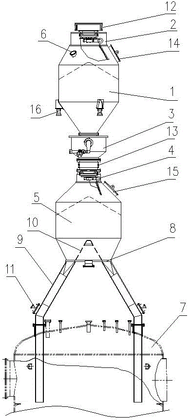
[0021] like figure 1 As shown, the shaft furnace top charging device in this embodiment includes a charging tank 1, an upper sealing valve 2 disposed on the inlet of the charging tank 1, and a material flow regulating valve disposed on the outlet of the charging tank 1 3. The lower sealing valve 4 connected to the outlet of the material flow regulating valve 3, the storage bin 5 connected to the outlet of the lower sealing valve 4, and the distributor connected to the outlet of the storage bin 5. A pressure equalizing interface 6 is provided.

[0022] The charging device on the top of the shaft furnace in this embodiment, under the working condition that the pressure in the storage bin 6 and above is higher than the normal pressure, that is, under the working condition with pressure, the charging is realized through the following process:

[0023] First...


PUM


Abstract

The invention discloses a top charging device of a shaft furnace, which comprises a charging tank, an upper sealing valve arranged on an inlet of the charging tank, a material flow regulating valve arranged on an outlet of the charging tank, a lower sealing valve connected with an outlet of the material flow regulating valve, a bunker connected with a discharging hole of the lower sealing valve, and a distributor connected with an outlet of the bunker, wherein a uniform pressure relief interface is arranged in the charging tank. According to the top charging device of the shaft furnace, the uniform pressure relief interface is connected with a uniform pressure relief device, so that a pressure in the charging tank can be regulated to reach a required value, the charging operation is realized on the bunker or a region above the bunker under the working condition of normal pressure, the smooth charging of the shaft furnace under the working condition of pressure is realized; and the top charging device can carry out charging operation under the working condition of normal pressure. The top charging device of the shaft furnace has the advantages of compact and simple structure, less devices, and lower building cost; and a modular design is adopted, all single devices can be separately maintained, the maintenance time can be greatly saved, and the maintenance cost is lowered.

Description

technical field [0001] The invention relates to the technical field of ironmaking equipment, in particular to a furnace top charging device for a shaft furnace. Background technique [0002] Due to its stable composition, low harmful impurities, uniform particle size and many other advantages, direct reduced iron plays an increasingly important role in the field of iron and steel metallurgy. In recent years, the growth rate of global direct reduced iron production has reached 9%, which shows that its development potential is quite huge. There are many kinds of direct reduced iron production techniques, among which the gas-based shaft furnace is the mainstream technology, and the output of direct reduced iron has accounted for about 75% of the total output. [0003] The furnace top charging device is the key equipment of the direct reduction shaft furnace, and its working performance directly affects the normal production of the shaft furnace. The shaft furnace is continuou...

Claims


Application Information

Patent Timeline
IPC IPC(8): C21B13/02F27B1/20
Inventor 王蜀生王涛戴文军郑军张涛郭敏陈凌
Owner CISDI ENG CO LTD
Why Eureka
Try Eureka