Gas stove

A gas stove and burner technology, applied in the field of kitchen utensils, can solve the problems of waste, heat loss, and inability to fully utilize the heat of gas combustion.

Active Publication Date: 2013-02-06
WUHU MIDEA SMART KITCHEN APPLIANCE MFG CO LTD
View PDF5 Cites 5 Cited by
  • Summary
  • Abstract
  • Description
  • Claims
  • Application Information

AI Technical Summary

Problems solved by technology

[0002] At present, the burners of ordinary domestic gas built-in cookers are usually placed on the panel of the cooker. In this kind of gas cooker structure, when the gas is burning, the flame is completely exposed in the air, and the heat generated by the combustion is caused by thermal radiation or convection with the air. Most of the heat is lost due to heat exchange, of which only about 50% of the hea

Method used


Image

  • Gas stove
  • Gas stove
  • Gas stove

Examples


Example Embodiment

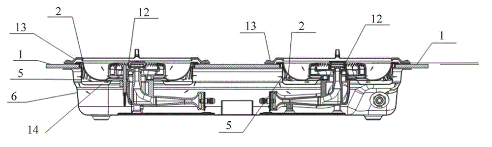
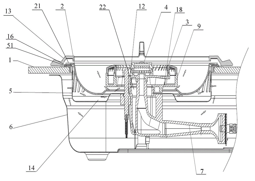
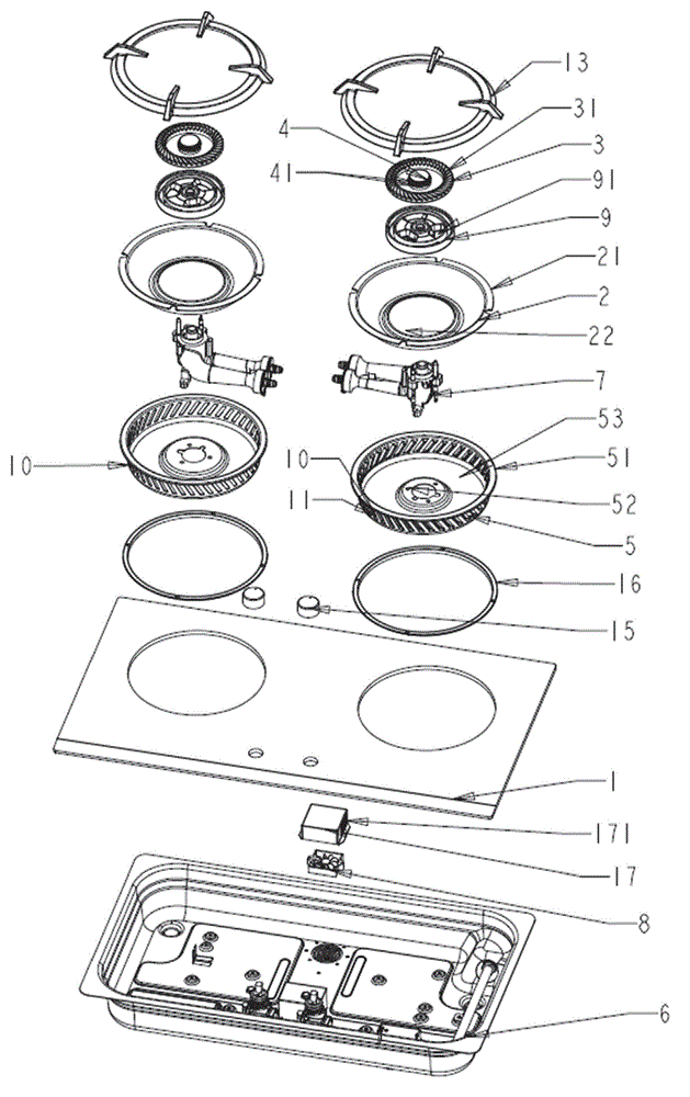
[0032] Such as Figure 1 to Figure 4 As shown, a gas stove proposed in this embodiment includes a panel with an opening 1, a bottom shell 6 supporting the panel 1, a burner assembly 12, and a pot bracket 13 provided at the opening of the panel 1. The burner assembly 12 A fire hole 41 and / or a fire groove 31 are provided on the gas stove. The gas stove also includes a bowl-shaped energy collecting plate 2 arranged at the opening of the panel 1, and the burner assembly 12 is located on the energy collecting plate 2 The fire hole 41 and / or the fire groove 31 of the burner assembly 12 are not higher than the top surface of the energy collecting plate 2.

[0033] In this embodiment, the burner assembly 12 is embedded in the energy collecting plate 2, and the fire hole 41 and / or the fire groove 31 of the burner assembly 12 is not higher than the top surface of the energy collecting plate 2, so that the fire hole of the burner assembly 12 The flame emitted by 41 and / fire trough 31 can ...


PUM


Abstract

The invention discloses a gas stove. The gas stove comprises a panel provided with an opening, a bottom case which is used for supporting the panel, a burner and an energy-collecting disk which is arranged at a position of the opening of the panel, wherein the burner is located in the energy-collecting disk, a pressurization disk is arranged on the lower portion of the energy-collecting disk, and a secondary air supplementing hole is arranged on the side wall of the pressurization disk. The energy-collecting disk is arranged on the surrounding of the burner and is used for conducting energy-collecting reflection for energy generated by the burner, the heat emission and the heat convection are greatly reduced, the gas burning heat efficiency is improved, the pressurization disk is arranged on the lower portion of the energy-collecting disk, the secondary air supplementing hole is arranged on the side wall of the pressurization disk, the air outside the pressurization disk enters from the secondary air supplementing hole and is used for supplementing the burner with the secondary air through the channel between the energy-collecting disk and the pressurization disk, a pressurization fan is arranged on the bottom case of the gas stove, an air duct structure is arranged on the surrounding of the pressurization fan, the burning is complete, the gas burning heat efficiency is improved further and the effect of the inner temperature increment of the gas stove is reduced.

Description

technical field [0001] The invention relates to the technical field of kitchen utensils, in particular to a built-in gas stove. Background technique [0002] At present, the burners of ordinary domestic gas built-in cookers are usually placed on the panel of the cooker. In this kind of gas cooker structure, when the gas is burning, the flame is completely exposed in the air, and the heat generated by the combustion is caused by thermal radiation or convection with the air. Most of the heat exchange is lost, of which only about 50% of the heat can be used, and the remaining half of the heat is wasted. [0003] In the existing built-in cookers, the burner is also placed under the panel of the cooker. However, its structure is relatively complicated, which not only increases the internal temperature rise of the cooker, but also cannot make full use of the combustion heat of the gas, resulting in a high thermal efficiency of the gas combustion. lower. Contents of the inventio...

Claims


Application Information

Patent Timeline
IPC IPC(8): F24C3/08F24C15/22
CPCY02B40/00
Inventor 王山伟贾贵胜张炳卫孙飞
Owner WUHU MIDEA SMART KITCHEN APPLIANCE MFG CO LTD
Why Eureka
Try Eureka