Optical network unit and optical module in optical network unit

An optical network unit and network unit technology, applied in the field of optical fiber communication, can solve the problems of signal quality degradation, ONU optical module transmission rate cannot reach 10 Gigabit or above, etc., to improve quality, enhance shock resistance, and increase reliability Effect

Active Publication Date: 2013-02-06
HISENSE BROADBAND MULTIMEDIA TECH
View PDF4 Cites 13 Cited by
  • Summary
  • Abstract
  • Description
  • Claims
  • Application Information

AI Technical Summary

Problems solved by technology

[0004] However, as the network rate increases, the signal quality will drop significantly when the ONU optical module transmits at a rate above 10 Gigabit; in other words, the transmission rate of the ONU optical module cannot reach 10 Gigabit or above at present.

Method used


Image

  • Optical network unit and optical module in optical network unit
  • Optical network unit and optical module in optical network unit
  • Optical network unit and optical module in optical network unit

Examples


Embodiment Construction

[0040] In order to make the object, technical solution and advantages of the present invention clearer, the present invention will be described in further detail below with reference to the accompanying drawings and preferred embodiments. However, it should be noted that many of the details listed in the specification are only for readers to have a thorough understanding of one or more aspects of the present invention, and these aspects of the present invention can be implemented even without these specific details.

[0041] As used herein, terms such as "module" and "system" are intended to include computer-related entities such as, but not limited to, hardware, firmware, a combination of hardware and software, software, or software in execution. For example, a module may be, but is not limited to being limited to being, a process running on a processor, a processor, an object, an executable, a thread of execution, a program, and / or a computer.

[0042] The inventor of the pr...


PUM


Abstract

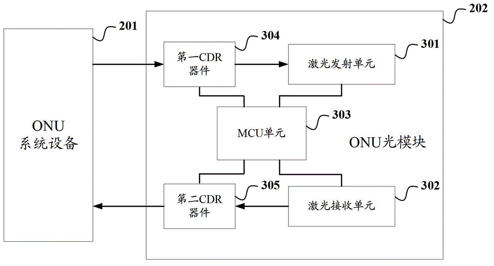
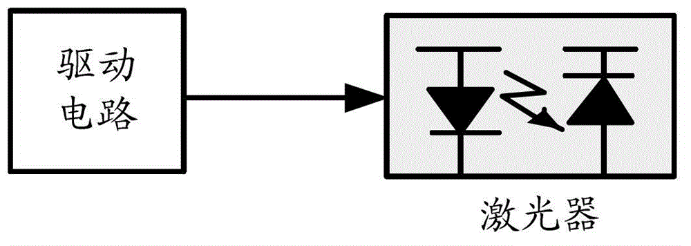
The invention discloses an optical network unit (ONU) and an optical module in the ONU. The optical module comprises a first CDR (Clock Data Recovery) device, a laser emission unit, a laser receiving unit and a second CDR device, wherein the first CDR device is used for receiving and integrating electrical signals transmitted by ONU system equipment and then outputting the electrical signals; the laser emission unit comprises a laser and a drive circuit of the laser; after receiving the electrical signals output by the first CDR device, the drive circuit drives the laser to emit uplink optical signals based on the received electrical signals; the laser receiving unit is used for receiving downlink optical signals and outputting responding electrical signals according to the received downlink optical signals; and the second CDR device is used for receiving and integrating the electrical signals output by the laser receiving unit, and outputting the electrical signals to the ONU system equipment. According to the invention, as the electrical signals transmitted by the ONU system equipment is reshaped and recovered by the CDR devices, the quality of the electrical signals input to the laser drive circuit is improved, thereby increasing the transmission rate of the uplink optical signals of the optical module in the ONU.

Description

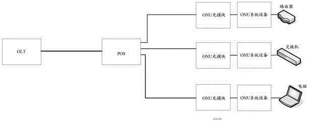
technical field [0001] The invention relates to optical fiber communication technology, in particular to an optical network unit and an optical network unit optical module. Background technique [0002] In the current domestic market and international market, the direction of optical fiber communication with high bandwidth, high speed and multi-service integration has begun to be applied; among many solutions, the emergence of fiber-to-the-home (FTTH) is considered to be the ultimate broadband access solution. [0003] FTTH networks are usually as figure 1 As shown, the OLT (Optical Line Terminal, Optical Line Terminal) of the central office is connected to the POS (Passive Optical Splitter, Passive Optical Splitter) through the ODN (Optical Feeder Network). If the input light intensity of the uplink port is 1, the output light intensity of each downlink port is 1 / N. For an FTTH network, generally 1 OLT is placed in the telecom central office, and then passes through the ...

Claims


Application Information

Patent Timeline
Patent Type & Authority Applications(China)
IPC IPC(8): H04Q11/00H04B10/40
Inventor 杨思更赵其圣薛登山何鹏
Owner HISENSE BROADBAND MULTIMEDIA TECH
Why Eureka
Try Eureka