Optical fiber displacement sensor with ultra-short baseline compliant cylinder structure and optical fiber strain gauge

A displacement sensor and ultra-short baseline technology, applied in the field of strain gauges, can solve the problems of being affected by humidity, electromagnetic interference, sensitivity and measurement accuracy, and output nonlinearity, and achieve the effect of reducing baseline scale and improving measurement accuracy.

Inactive Publication Date: 2013-02-13
HARBIN ENG UNIV
View PDF7 Cites 14 Cited by
  • Summary
  • Abstract
  • Description
  • Claims
  • Application Information

AI Technical Summary

Problems solved by technology

[0008] Displacement sensors currently invented in strain gauges mainly use eddy current displacement sensors, differential transformer displacement sensors, or capacitive displacement sensors, among which the best displacement resolution of the first two is about 1 nanometer; The force can reach 0.01 nanometers, but there are shortcom

Method used


Image

  • Optical fiber displacement sensor with ultra-short baseline compliant cylinder structure and optical fiber strain gauge
  • Optical fiber displacement sensor with ultra-short baseline compliant cylinder structure and optical fiber strain gauge
  • Optical fiber displacement sensor with ultra-short baseline compliant cylinder structure and optical fiber strain gauge

Examples


Embodiment Construction

[0051] The present invention will be further described below in conjunction with the examples and accompanying drawings, but the protection scope of the present invention should not be limited thereby.

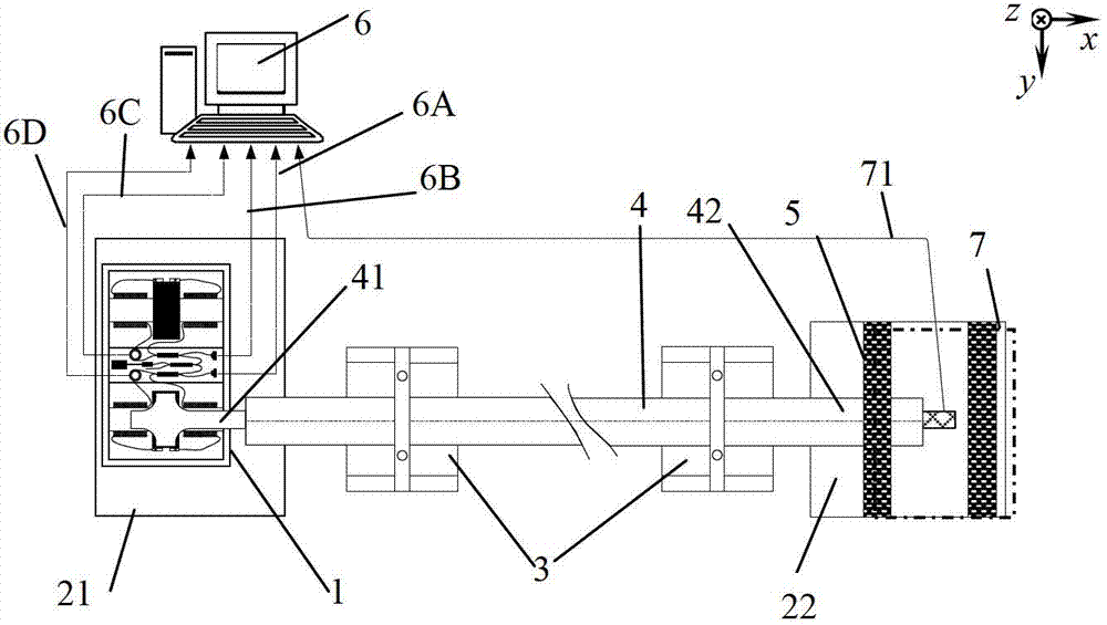
[0052] combine figure 1 . The optical fiber strain gauge consists of a displacement sensor 1, a measuring baseline rod 4, a baseline fixing device 5, measuring bedrock 21, 22, a suspension system 3, a measurement control, signal recording and processing system 6, and a measurement calibration device 7, and is characterized in that : The variable cylindrical optical fiber displacement sensor 1 fixed on the first bedrock 21 is connected to one end 41 of the measurement baseline 4; the other end 42 of the measurement baseline 4 is equipped with a measurement calibration device 7, and is fixed on the second On the bedrock 22; the suspension system 3 is installed in the middle of the measurement baseline 4; the variable cylindrical optical fiber displacement sensor 1 and the measu...


PUM


Abstract

The invention provides an optical fiber displacement sensor with an ultra-short baseline compliant cylinder structure and an optical fiber strain gauge. The optical fiber strain gauge comprises an optical fiber displacement sensor body (1), a measure baseline (4), a baseline fixing device (5), a suspension system (3), a measure control and signal recording and processing system (6) and a measurement calibration device (7); the optical fiber displacement sensor body (1) is fixed on a first bed rock (21) and connected with the head end (41) of the measure baseline (4); the tail end (42) of the measure baseline (4) is provided with the measurement calibration device (7) and fixed on a second bed rock (22) through the baseline fixing device (5); the suspension system (3) is arranged in the middle of the measure baseline (4), and the displacement sensor (1) and the measurement calibration device (7) are connected with the measure control and signal recording and processing system (6) through a signal connecting wire. The optical fiber displacement sensor is applied to a geophysical research, observation of crustal strain and solid tide, obtaining of earthquake precursor information and the like.

Description

technical field [0001] The invention relates to an optical fiber sensing and measuring device, in particular to an optical fiber displacement sensor used for geophysical research, observation of crustal strain and solid tide, and acquisition of earthquake precursor information, and a strain sensor composed of the optical fiber displacement sensor. instrument. Background technique [0002] The strain gauge is an instrument that precisely measures the relative change of the distance between two points in the crustal rock mass. It has important applications in the fields of observing crustal strain and solid tides, as well as studying the process of earthquake breeding and obtaining earthquake precursors. [0003] Since the American seismologist H. Benioff developed the first valuable quartz extensometer in 1935, the United States, Britain, the former Soviet Union, Japan, Belgium, Germany and other countries have successively developed high-sensitivity extensometers. instrumen...

Claims


Application Information

Patent Timeline
IPC IPC(8): G01B11/02G01B11/16
Inventor 吴冰杨军彭峰苑勇贵苑立波
Owner HARBIN ENG UNIV
Why Eureka
Try Eureka