Experimental device for reducing heat flow rate by applying local reverse overflow of aircraft

A technology of experimental equipment and aircraft, applied in the field of experimental equipment, can solve the problem of large drag reduction effect and achieve the effect of reducing heat flow

Inactive Publication Date: 2013-02-13
INST OF MECHANICS - CHINESE ACAD OF SCI
View PDF4 Cites 10 Cited by
  • Summary
  • Abstract
  • Description
  • Claims
  • Application Information

AI Technical Summary

Problems solved by technology

It is found that the pressure ratio of plasma injection is under certain circumstances, although the momentum is smaller than that of cold flow injection, but the drag reduction effect is much greater than that

Method used


Image

  • Experimental device for reducing heat flow rate by applying local reverse overflow of aircraft
  • Experimental device for reducing heat flow rate by applying local reverse overflow of aircraft
  • Experimental device for reducing heat flow rate by applying local reverse overflow of aircraft

Examples


Embodiment Construction

[0024] Because the protected area is narrow and the amount of liquid used is very small, there is almost no interference with the mainstream.

[0025] An aircraft with a large lift-to-drag ratio (such an aircraft usually has a conical head) is used as an example for illustration.

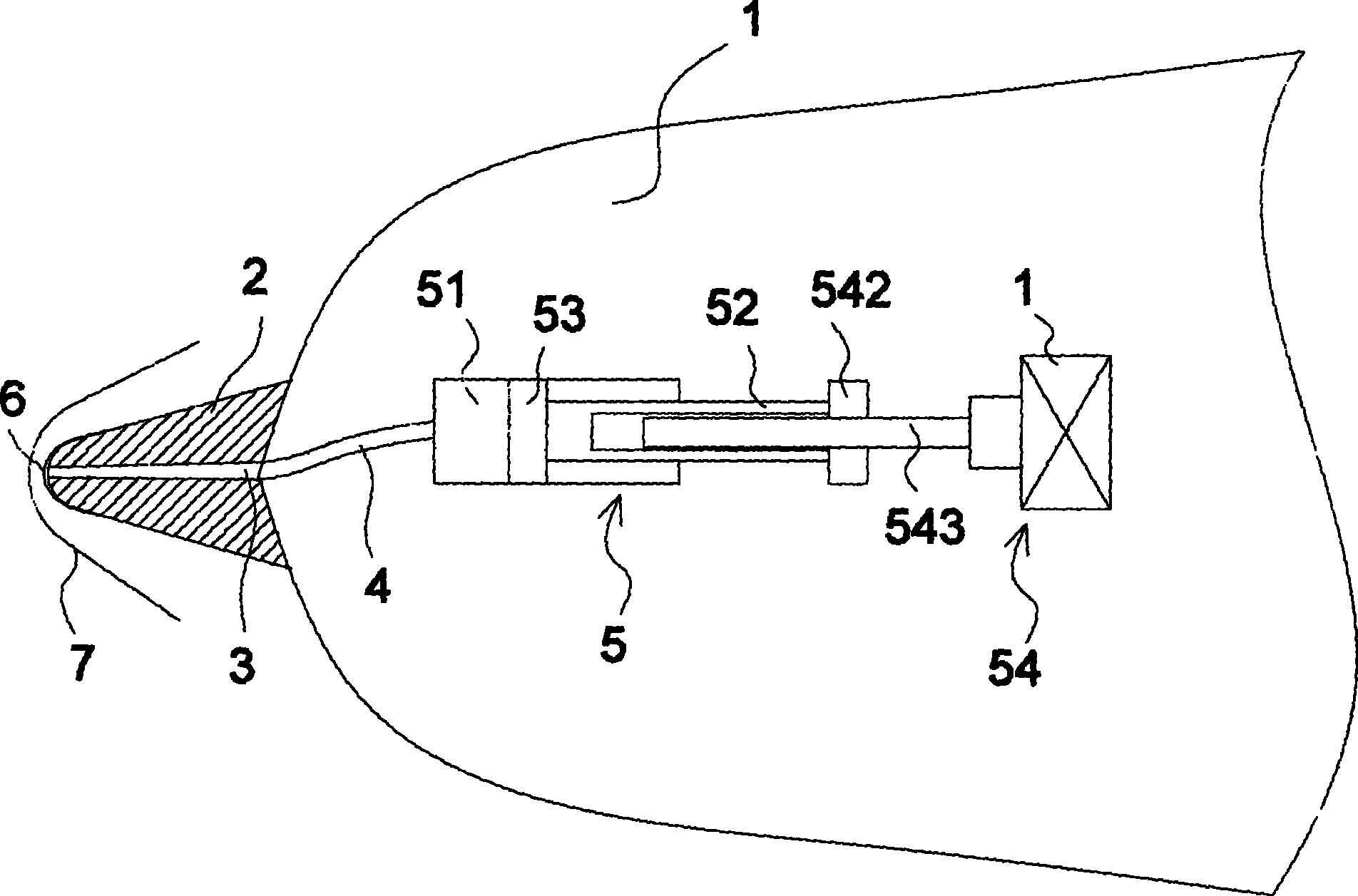
[0026] like figure 1 As shown, the experimental device of the present invention includes: a simulated aircraft shell 1, the shell 1 has a pointed cone head 2, for an aircraft with a pointed cone head 2 like this, the position of the head 2 belongs to the region of high heat flow . The tip of the cone head 2 is provided with an opening 3, and then one end of the conduit 4 is connected to the opening 3, and the other end is connected to a liquid injection device 5 that can continuously inject liquid, and the liquid injection device 5 can be controlled according to a predetermined The flow rate and time are used to inject liquid into opening 3. In the present invention, the injected liquid is water....


PUM


Abstract

The invention discloses an experimental device for reducing heat flow rate of local reverse overflow of an aircraft, which comprises a simulation aircraft shell, more than one opening holes, a guide pipe, a liquid injection device and a control device, wherein the opening holes are formed on the surface of a pre-detected high heat flow region of the shell, one end of the guide pipe is communicated with the opening hole, the liquid injection device is connected with the other end of the guide pipe and is used for injecting liquid to the guide pipe, the control device is used for controlling liquid at pre-determined flow injected by the liquid injection device within a preset time. Normal-temperature liquid continuously overflowing out of the surface of the local high heat flow region of the aircraft shell is simulated; when the aircraft flies at high speed, a liquid can form a thin film layer on the surface of the local high heat flow region; a small amount of liquid overflows, the area of the thin layer formed on the surface is small, the local high heat flow region is mainly cover, so that almost no interference is generated on main stream of the aircraft.

Description

technical field [0001] The invention relates to an experimental device for reducing heat flow rate by partial reverse overflow of an aircraft. Background technique [0002] The earliest studies on flood cooling were tangential jets to form a film to reduce the heat flow. In 1946, Wieghardt conducted research on hot air deicing to solve the problem of wing icing. In 1966, Goldstein et al first carried out experimental research on tangential sonic jet flow in Ma=3 supersonic flow. In 1970, Parthasarthy and Zakkay performed an experimental study on the near-tangential injection of different refrigerants (helium, hydrogen and argon) in the mainstream of Ma=6. From 1970 to 1971, Cary and Hefner conducted experimental research on flat film cooling in the mainstream of Ma=6, and the refrigerant was air. [0003] Their research found that the film cooling effect of Ma=6 supersonic flow is significantly higher than that of subsonic and Ma<6 supersonic flow under the same inject...

Claims


Application Information

Patent Timeline
Patent Type & Authority Applications(China)
IPC IPC(8): G01M9/00
Inventor 陈宏陈兵张仕忠
Owner INST OF MECHANICS - CHINESE ACAD OF SCI
Why Eureka
Try Eureka