Light beam collimator

A collimator and beam technology, applied in optics, instruments, optical components, etc., can solve the problems that light cannot be coupled, the system size is large, and the use is affected, so as to improve the collection ability, reduce the divergence angle, and reduce the size of the system. Effects of Size and Complexity

Active Publication Date: 2013-02-13
江苏大学扬州(江都)新能源汽车产业研究所
View PDF4 Cites 0 Cited by
  • Summary
  • Abstract
  • Description
  • Claims
  • Application Information

AI Technical Summary

Problems solved by technology

When using lenses or reflectors to converge sunlight or wide-aperture parallel or quasi-parallel beams, although the structure is simpler and the focusing surface can be larger, if the focused spot is generated at a longer distance, the size of the entire system will be reduced. Will be very large, affecting its actual use
If you want to generate a focused spot at a short distance, the angle between the beam and the axis of the lens at the focal point is very large, while the focusing angle of the optical fiber is not large, which leads to the fact that some light cannot be coupled into the optical fiber

Method used


Image

  • Light beam collimator
  • Light beam collimator
  • Light beam collimator

Examples


Embodiment 1

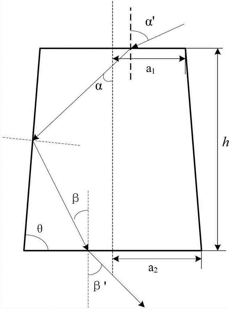
[0038] The round platform is composed of pure quartz, the surface is smooth, and the small circle radius a 1 =10mm, the inclination angle of the circular platform γ=13.3°, and the height of the circular platform h=16.6mm. The beam with inner divergence angle α=40° (divergence angle α′=68.8°) can be collimated into a collimated beam with inner exit angle β=13.3° (output angle β′=19.5°). great circle radius a 2 =13.9mm, that is, the spot area only increases by 93%.

Embodiment 2

[0040] The round platform is composed of pure quartz, the sides are coated with a thin layer of metallic silver, and the radius of the small circle is a1 =15mm, the inclination angle of the circular platform γ=9°, and the height of the circular platform h=21mm. The beam with inner divergence angle α=30° (divergence angle α′=46.5°) can be collimated into a collimated beam with inner output angle β=12° (output angle β′=17.6°). great circle radius a 2 =18.3mm, that is, the spot area only increases by 49%.

Embodiment 3

[0042] The circular platform is composed of polymer material, the surface is smooth, and the small circle radius a 1 =20mm, the inclination angle of the circular platform γ=10°, and the height of the circular platform h=30mm. The beam with inner divergence angle α=30° (divergence angle α′=48.2°) can be collimated into a collimated beam with inner output angle β=10° (output angle β′=15°). great circle radius a 2 =25.3mm, that is, the spot area is only increased by 60%.


PUM

PropertyMeasurementUnit
Heightaaaaaaaaaa

Abstract

The invention discloses a novel light beam collimator for collimating non-collimated light beams. The collimator is a circular table formed by transparent media, namely, formed by a cone by removing a small cone at the top. The light beams enter from a small circle and are output from a large circle. The upper and lower surfaces of the circular table are smooth, effective input and output are achieved, and the lateral side of the circular table is a smooth surface or coated with a high reflection metal film to achieve effective reflection for lights entering from the inside of the circular table to the lateral side of the circular table. The collimator can shape light beams with large divergence angles into light beams with small divergence angles and can be applied to sunlight collecting systems, laser beam collimation and the like; and therefore the collecting capacity of a follow-up condenser to the lights is effectively improved, and the problem that common condensers cannot effectively converge the lights into optical fibers for transmission due to large divergence angles of condensed lights is solved.

Description

technical field [0001] The invention relates to the fields of solar energy development, laser application, LED lighting and the like, in particular to a sunlight optical fiber lighting device. Background technique [0002] In systems such as solar collectors, it is necessary to converge the light through a focusing system such as a lens or a mirror, so as to input it into a transmission medium with a small cross-section such as an optical fiber. At present, the general concentrator is composed of multiple arrays to achieve efficient sunlight collection. For example, the invention patent "sunlight fiber optic lighting device (CN01113529)" adopts a high-sensitivity sensor composed of a condenser lens and a four-quadrant photovoltaic detector to achieve stable and reliable sunlight tracking. When using lenses or reflectors to converge sunlight or wide-aperture parallel or quasi-parallel beams, although the structure is simpler and the focusing surface can be larger, if the foc...

Claims


Application Information

Patent Timeline
IPC IPC(8): G02B27/30G02B27/09
Inventor 陈明阳张银
Owner 江苏大学扬州(江都)新能源汽车产业研究所
Why Eureka
Try Eureka