Antenna element and multiple-input multiple-output (MIMO) antenna device

An antenna element and antenna device technology, which is applied to devices, antennas, electrical components, etc. that make the antenna work in different frequency bands at the same time, can solve the problems of high utilization rate of antenna radiation area and strong anti-interference ability.

Active Publication Date: 2013-02-13
KUANG CHI INST OF ADVANCED TECH
View PDF10 Cites 5 Cited by
  • Summary
  • Abstract
  • Description
  • Claims
  • Application Information

AI Technical Summary

Problems solved by technology

[0004] The technical problem to be solved by the present invention is to break through the framework of traditional antenna design, save the complicated design of impedance matching network, e...

Method used


Image

  • Antenna element and multiple-input multiple-output (MIMO) antenna device
  • Antenna element and multiple-input multiple-output (MIMO) antenna device
  • Antenna element and multiple-input multiple-output (MIMO) antenna device

Examples


Embodiment Construction

[0027] The present invention will be further described below in conjunction with accompanying drawing and specific embodiment:

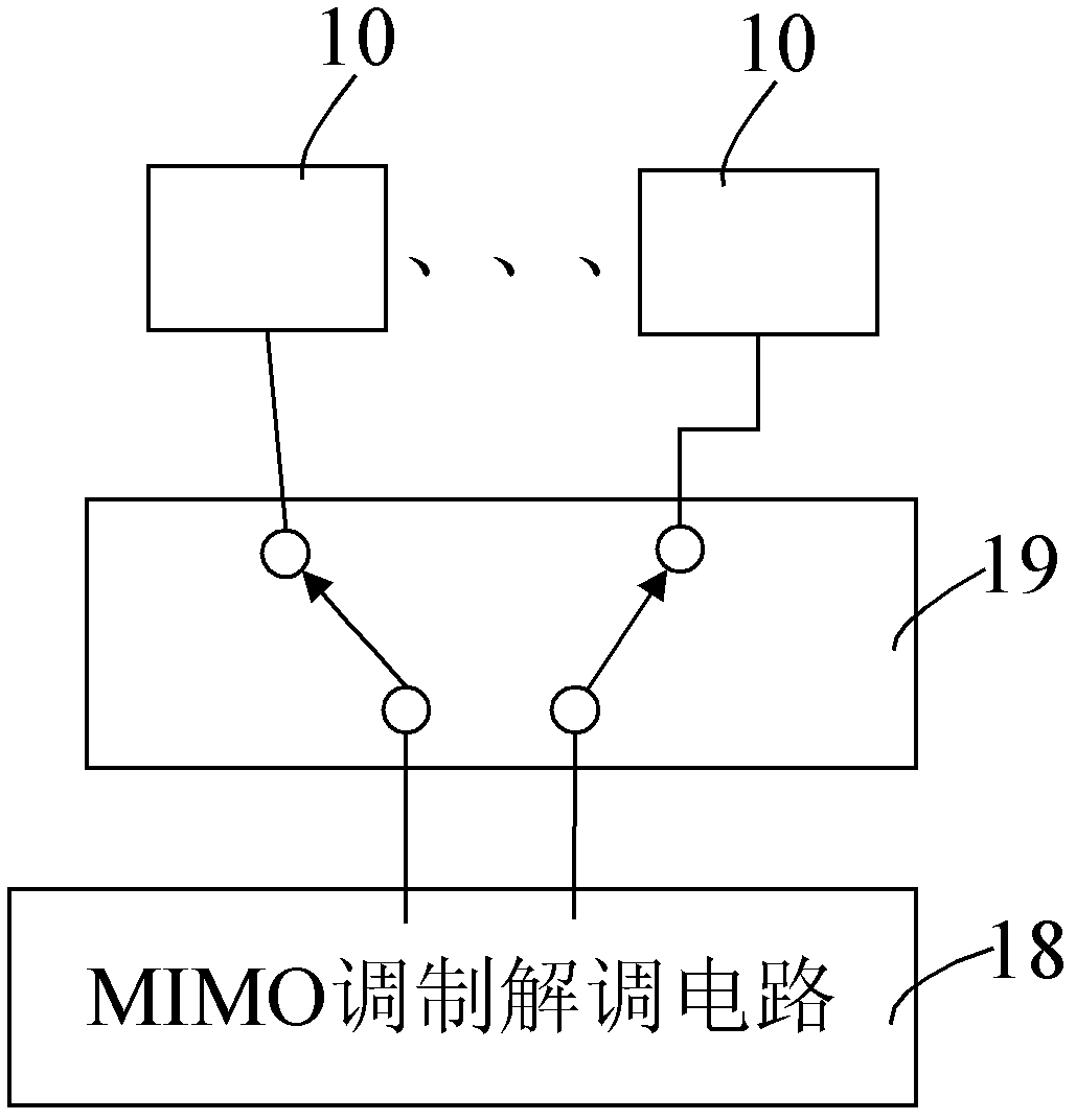
[0028] see figure 1 , the MIMO antenna device includes an antenna element 12 , a switching unit 19 and a MIMO modulation and demodulation circuit 18 . Described antenna element 12 comprises two antenna units 10, and the feeding point of each antenna unit 10 extends outwards and becomes pin, and each antenna unit 10 is connected with switching unit 19 one by one through described pin; MIMO modulation and demodulation The circuit 18 receives the electrical signals of the at least two antenna units 10 and transmits the electrical signals to the at least two antenna units 10 through the switching unit 19 .

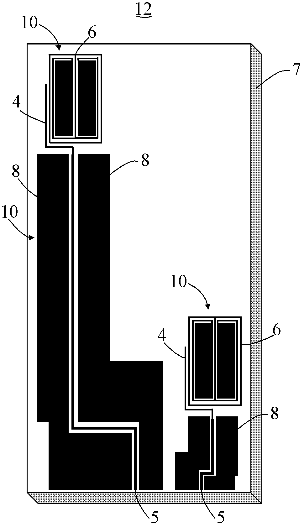
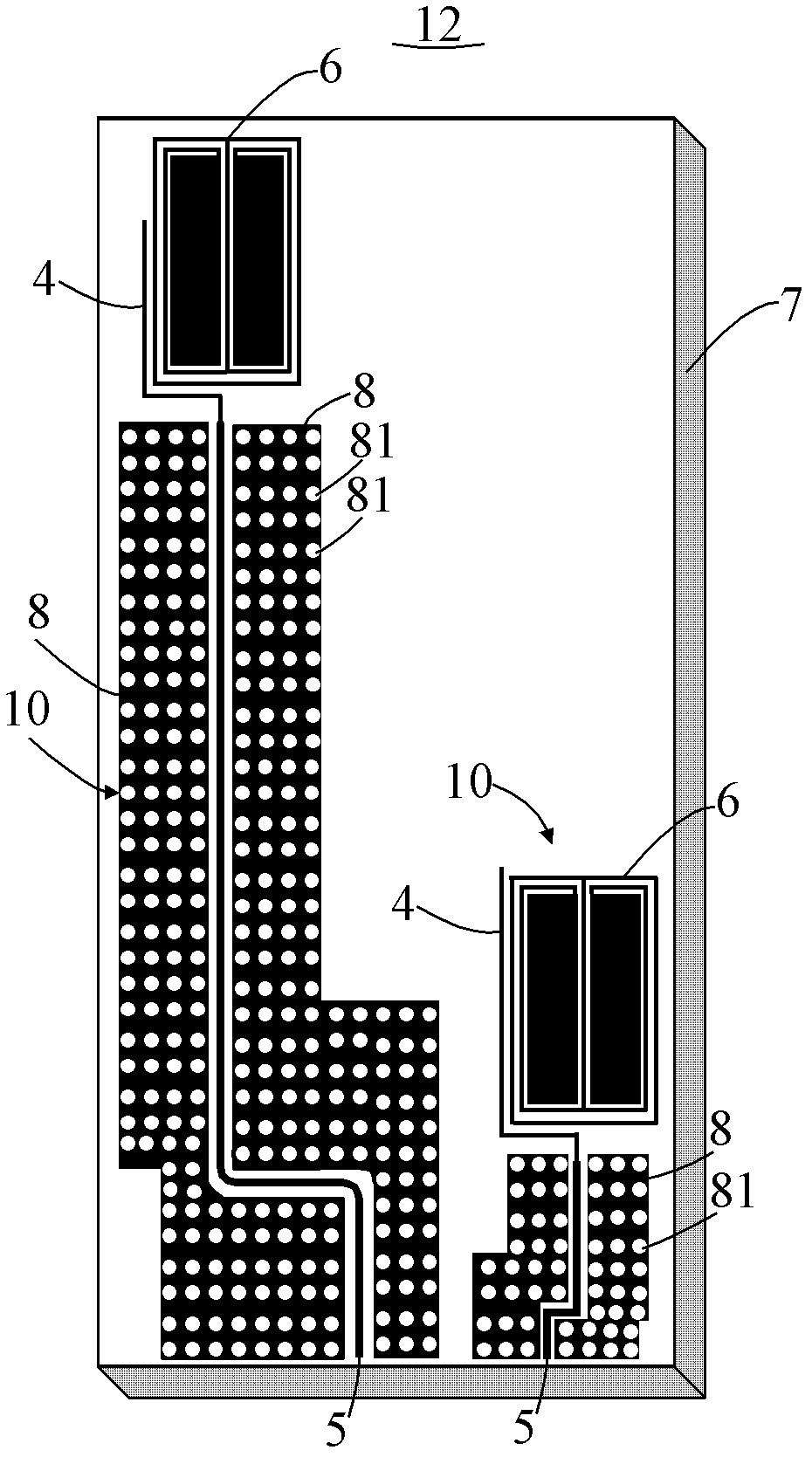
[0029] see figure 2 , is a structural schematic diagram of a specific embodiment of the antenna element. The antenna element 12 includes a dielectric substrate 7 and two antenna units 10 disposed on a surface of the dielectric substrate 7 . The ...


PUM


Abstract

The invention relates to an antenna element. The antenna element comprises a dielectric substrate and at least two antenna units arranged on the dielectric substrate, wherein each antenna unit comprises a feed unit, grounding units arranged on the two sides of the feed unit, a feed line connected with the feed unit, and a metal structure; the feed line is coupled with the metal structure through an electric signal; and at least two antenna units have at least two electromagnetic wave resonant communication frequency ranges. A related electromagnetic wave resonant response metal structure library is made of a manual electromagnetic material, and the structures are small compared with the traditional antenna structure, so that the physical size of antennae is not limited by the physical length of half-wavelength; the corresponding antenna units are made on the basis of the metal structures; and the information sending or receiving throughput of a plurality of antenna units is improved on the basis of an MIMO technology.

Description

technical field [0001] The present invention relates to a communication antenna, and more specifically, to an antenna element and a MIMO (Multiple-Input Multiple-Out-put) antenna device including the antenna element. Background technique [0002] With the high development of semiconductor technology, higher and higher requirements are put forward for the integration of today's electronic systems, and the miniaturization of devices has become a technical issue of great concern to the entire industry. However, unlike the development of IC chips following "Moore's Law", radio frequency modules, another important component of electronic systems, face the difficult technical challenge of device miniaturization. The radio frequency module mainly includes main components such as frequency mixing, power amplifier, filter, radio frequency signal transmission, matching network and antenna. Among them, the antenna is the radiating unit and receiving device of the final radio frequency...

Claims


Application Information

Patent Timeline
IPC IPC(8): H01Q1/36H01Q1/38H01Q5/01H01Q5/10
Inventor 刘若鹏徐冠雄方能辉李岳峰
Owner KUANG CHI INST OF ADVANCED TECH
Why Eureka
Try Eureka