High-power high-speed permanent magnet generator rotor surface-mounting type fixing permanent magnet structure and method

A permanent magnet generator and permanent magnet technology, which is applied in the direction of magnetic circuit shape/style/structure, manufacturing stator/rotor body, magnetic circuit rotating parts, etc., can solve problems that affect work safety and permanent magnets are not firmly fixed, etc. To achieve the effect of safe work, firm fixation and convenient assembly

Inactive Publication Date: 2013-02-13
SHANDONG SHANBO ELECTRIC MACHINE GROUP
View PDF4 Cites 6 Cited by
  • Summary
  • Abstract
  • Description
  • Claims
  • Application Information

AI Technical Summary

Problems solved by technology

[0002] The high-power high-speed permanent magnet generator with a generator speed of up to 7000 rpm and a power of 360kW is developed for the maglev magnetodynamic wind power storage power station. It is a new type of wind power generation device with high generator efficiency and energy saving. , green and environmental protection, and can also be applied to industrial equipment, such as fans, water pumps, printing machinery, textile machinery, petroleum, chemical industry, metallurgy, etc. The general permanent magnet generator speed does not exceed 3000 rpm, and the traditional wind turbine speed is generally No more than 1000 rpm, because the high-power high-speed permanent magnet generator speed can reach 7000 rpm, and the outer diameter of the rotor is pasted with permanent magnets. When rotating at high speed, the centrifugal force of the permanent magnets is very large, reaching 5.9MPa, which is higher than The centrifugal force of a large turbogenerator is much greater, so during normal operation, there are factors such as the permanent magnet not being firmly fixed and affecting work safety.

Method used


Image

  • High-power high-speed permanent magnet generator rotor surface-mounting type fixing permanent magnet structure and method
  • High-power high-speed permanent magnet generator rotor surface-mounting type fixing permanent magnet structure and method
  • High-power high-speed permanent magnet generator rotor surface-mounting type fixing permanent magnet structure and method

Examples


Embodiment Construction

[0023] Figure 1~4 It is the best embodiment of the present invention, below in conjunction with attached Figure 1~4 The present invention will be further described.

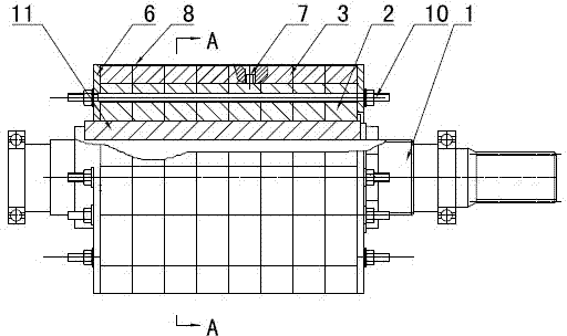
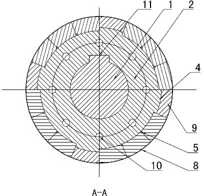
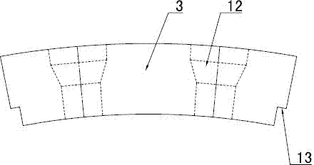
[0024] Refer to attached Figure 1~2 : The high-power high-speed permanent magnet generator rotor surface-mounted fixed permanent magnet structure includes a motor shaft 1, and the motor shaft 1 is covered with a rotor core 2 formed by axially stacking multiple rotor punches. 2. There is a motor shaft hole with a keyway in the center. The motor shaft 1 traverses the motor shaft hole and is connected with the rotor core 2 through the key 11 in the keyway. The outer raised pole spacers 4, four pole spacers 4 divide the outer surface of the rotor core 2 into 4 permanent magnet areas, and the surface of each permanent magnet area is evenly distributed along the axial direction with two poles for positioning the permanent magnets 3 Boss 5, the surface of the permanent magnet area is pasted and fixed by high-stren...


PUM


Abstract

The invention discloses a high-power high-speed permanent magnet generator rotor surface-mounting type fixing permanent magnet structure and method and belongs to the field of permanent magnet generator devices and manufacturing methods. The high-power high-speed permanent magnet generator rotor surface-mounting type fixing permanent magnet structure and method is characterized in that a plurality of bosses (5) used to position permanent magnets (3) are uniformly distributed on the surface of each permanent magnet area along the axial direction, a plurality of spliced permanent magnets (3) are fixed on the surface of each permanent magnet area through high-strength adhesives, two neighboring permanent magnets (3) in circumferential direction are separated and positioned through the bosses (5), the permanent magnets (3) are fastened with rotor cores (2) together through fastening bolts (7), carbon fiber binding belts (8) are wound on the outer surfaces of the permanent magnets (3), and rotor baffles (6) are fixedly arranged on two ends of the permanent magnets (3) in the axial direction. The high-power high-speed permanent magnet generator rotor surface-mounting type fixing permanent magnet structure and method enables the permanent magnets to overcome centrifugal force, maintain fixed and firm and work safely.

Description

technical field [0001] The invention discloses a surface-mounted fixed permanent magnet structure and method for a rotor of a high-power high-speed permanent magnet generator, belonging to the field of permanent magnet generator equipment and manufacturing methods, and specifically relates to a permanent magnet fixing structure and a fixing method of a high-power high-speed permanent magnet generator. Background technique [0002] The high-power high-speed permanent magnet generator with a generator speed of up to 7000 rpm and a power of 360kW is developed for the maglev magnetodynamic wind power storage power station. It is a new type of wind power generation device with high generator efficiency and energy saving. , green and environmental protection, and can also be applied to industrial equipment, such as fans, water pumps, printing machinery, textile machinery, petroleum, chemical industry, metallurgy, etc. The general permanent magnet generator speed does not exceed 300...

Claims


Application Information

Patent Timeline
Patent Type & Authority Applications(China)
IPC IPC(8): H02K15/03H02K1/28
Inventor 林江薄兆利杨洪卿张杰
Owner SHANDONG SHANBO ELECTRIC MACHINE GROUP
Why Eureka
Try Eureka