
Cascaded high-voltage inverter

A high-voltage frequency converter and frequency converter technology, applied in the field of high-voltage frequency converters, can solve the problems of a large number of switches, complicated system connections, and reduced system output capacity, etc., to save equipment and plant investment, simple system structure, and improve system output. The effect of capacity

Inactive Publication Date: 2013-02-13
ZHUZHOU NAT ENG RES CENT OF CONVERTERS
View PDF7 Cites 11 Cited by
  • Summary
  • Abstract
  • Description
  • Claims
  • Application Information

AI Technical Summary

Problems solved by technology

However, in the above literature, in order to achieve constant power output at various voltage levels, the series and parallel combinations of power modules are realized by continuously folding the converter link in half. This topology has a large number of switches and the system connection is more complicated.
At the same time, the parallel current sharing effect of the circuit topology is completely determined by the consistency of the system itself. Due to the differences in the inverter power module parameters or the inherent characteristics of the control system, the output voltages of different branches cannot be completely consistent. The resistance is only the wire resistance, and its value is very small, which will easily cause circulation between different parallel branches of the system and reduce the overall output capacity of the system

Method used


Image

  • Cascaded high-voltage inverter
  • Cascaded high-voltage inverter
  • Cascaded high-voltage inverter

Examples


Embodiment Construction

[0036] The following will clearly and completely describe the technical solutions in the embodiments of the present invention with reference to the accompanying drawings in the embodiments of the present invention. Obviously, the described embodiments are only part of the embodiments of the present invention, not all of them. Based on the embodiments of the present invention, all other embodiments obtained by persons of ordinary skill in the art without creative efforts fall within the protection scope of the present invention.

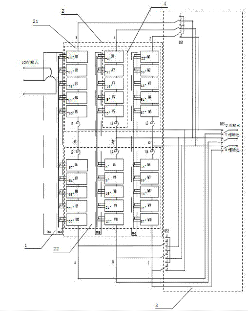
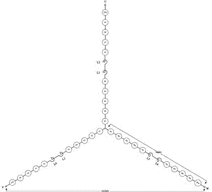
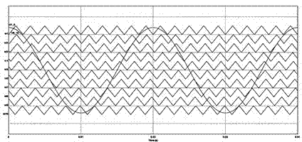
[0037] as attached figure 1 To attach Figure 10 As shown, a specific embodiment of a cascaded high-voltage frequency converter of the present invention is given, and the present invention will be further described below in conjunction with the drawings and specific embodiments.

[0038] as attached figure 1 A specific implementation of a cascaded high-voltage frequency converter is shown, including: a phase-shifting transformer 1 , a frequency conv...


PUM


Abstract

The invention discloses a cascaded high-voltage inverter. The high-voltage inverter comprises a phase-shifting transformer, an inverter and a multi-position selector switch assembly, wherein the inverter is connected with the phase-shifting transformer, and the multi-position selector switch assembly is connected with the inverter; each phase of the inverter further comprises two basic converting chains, and each basic converting chain comprises an H bridge power unit and a sharing reactor; a three-phase voltage is input into the phase-shifting transformer, and supplied as power to the H bridge power unit of the inverter after being reduced through the phase-shifting transformer; the H bridge power unit outputs a single-phase alternating voltage through rectification, filtration and inversion; and the serial and parallel connection mode and output mode of each basic converting chain can be changed by changing the on-off state of the multi-position selector switch assembly. According to the cascaded high-voltage inverter, a plurality of H bridge power units are serially connected to form minimum basic converting chains, and the serial and parallel connection combinations and star / triangular conversion of a plurality of basic converting chains are controlled by shifting a multi-position switch, so that full capacity output of various voltage-level converters can be realized, and the inverter is simple in structure and multi-purpose.

Description

technical field [0001] The invention relates to a high-voltage frequency converter, in particular to a cascaded high-voltage frequency converter with multiple voltage levels and full-capacity output. Background technique [0002] With the development of power electronic devices, high-voltage frequency converters, as electrical transmission equipment for driving various types of motors, have been more and more widely used in various fields of the national economy. Among the high-voltage inverters with many topological structures, the multi-level high-voltage inverter (cascaded high-voltage inverter) with H-bridge power units connected in series can realize high-voltage and large-capacity output with relatively low voltage-resistant devices, and the harmonics of the power grid The pollution is small, and the dv / dt of the output voltage of the motor is small. It has become one of the most mainstream and widely used forms of high-voltage inverters. [0003] The general voltage ...

Claims


Application Information

Patent Timeline
IPC IPC(8): H02M5/458
Inventor 彭勃罗仁俊曹洋蓝德邵范伟陈孟君张志李嘉黄欢肖伟李党盈王龙彭力南永辉黄迪刘永丰
Owner ZHUZHOU NAT ENG RES CENT OF CONVERTERS
Learn More