
Cleaning system

A cleaning and cleaning brush technology, applied in the field of cleaning systems, can solve problems such as electrostatic damage, damaged materials, and difficulty in foreign matter adsorption, and achieve the effect of preventing electrostatic damage and excellent maintainability

Active Publication Date: 2013-02-13
BANDO CHEM IND LTD
View PDF8 Cites 8 Cited by
  • Summary
  • Abstract
  • Description
  • Claims
  • Application Information

AI Technical Summary

Problems solved by technology

Therefore, there is no need to perform maintenance work on the cleaning roller, and it is difficult to continue the foreign matter adsorption operation by the cleaning roller for a long time.
[0009] In addition, in the case of attracting foreign matter by electrostatic force (Coulomb force), the side with more charges held on the roller surface of the above-mentioned clean roller becomes stronger. However, if the voltage on the roller surface of the clean roller becomes too large, Spark discharge occurs between the cleaning roller and the material to be cleaned as the counterpart material, spots are generated on the roller surface of the cleaning roller and the charged state of the material to be cleaned, foreign matter is attracted by the spots, and stable cleaning may not be performed. Possibility of performance
In addition, due to spark discharge, there is a possibility of damaging the opposing material
Furthermore, when the material to be cleaned is an electronic component such as a semiconductor with weak electrostatic force, even if the accumulation of charge does not reach the spark discharge, the electrostatic force destruction that occurs may become a problem

Method used


Image

  • Cleaning system
  • Cleaning system
  • Cleaning system

Examples


Embodiment 1

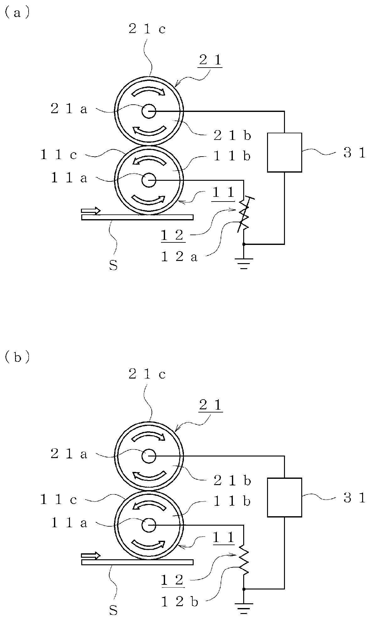
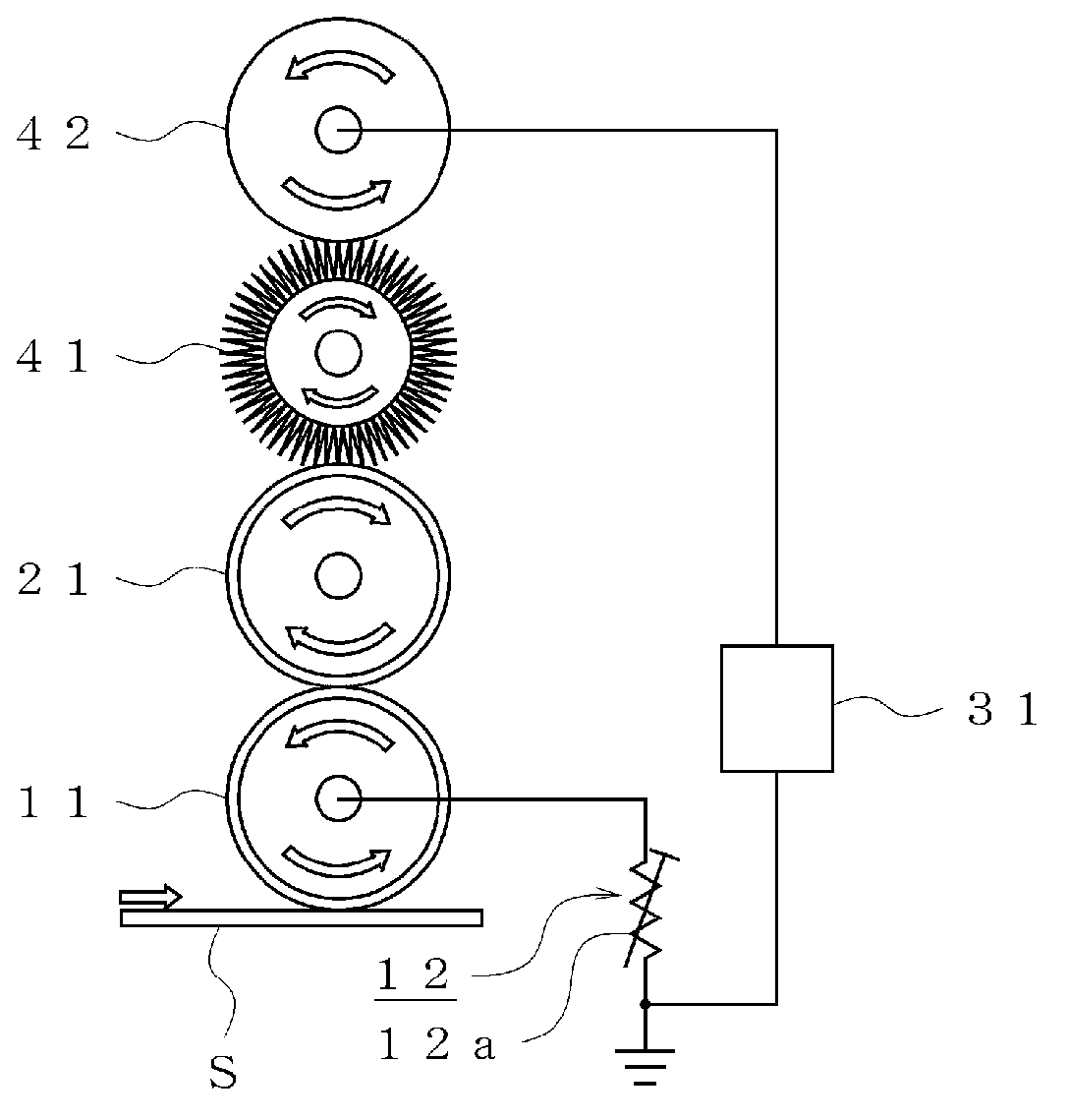
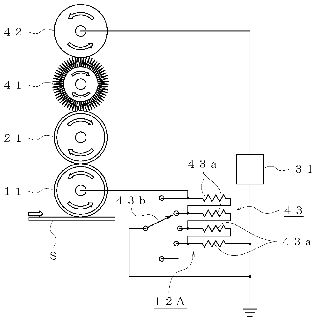
[0103] exist figure 2 In the cleaning system shown, the cleaning roller 11 and the transfer roller 21 held by an insulating member (not shown) are brought into contact with each other and rotated at a peripheral speed of 5 m / min. The ground line is provided through the variable resistor 12a. In addition, the external power supply 31 is connected to the metal roller 42 provided via the cleaning brush 41 to the transfer roller 21 . The cleaning brush 41 is set so as to face the transfer roller 21 and rotate in the direction opposite to the driving rotation direction, and the metal roller 42 is set so as to face the cleaning brush 41 and rotate in the driving rotation direction.

[0104] In the above state, the surface potential of each member with respect to the change in the resistance value of the variable resistor 12 a was measured using a surface potentiometer (Model 341B manufactured by Trek Corporation).

[0105] Table 1

[0106]

[0107] From this measurement resul...

Embodiment 2

[0129] exist Figure 13 In the cleaning system shown, the cleaning roller 11 and the transfer roller 21 held by an insulating member (not shown) are brought into contact with each other, and rotated at a peripheral speed of 5 m / min. On the core metal of the cleaning roller 11 A ground line is provided through a first voltage stabilizing circuit 13A (zener diode 13 a ) constituted by a Zener diode 13 a (Zener diode). In addition, with respect to the transfer roller 21, a cleaning brush 41 and a metal roller 42 are provided, and a second voltage stabilizing circuit 15A (zener diode 15a) is provided between the cleaning roller 11 and the core metal of the transfer roller 21. A third voltage stabilization circuit 16A (zener diode 16a) is provided between the printing roller 21 and the core metal of the cleaning brush 41, and a fourth voltage stabilization circuit is provided between the cleaning brush 41 and the core metal of the metal roller 42 17 (variable resistor 17a). The c...


PUM


Abstract

Provided is a system in which the adsorption of foreign matter by a cleaning roller can be continued for a prolonged period of time without performing maintenance operations on the cleaning roller. The disclosed cleaning roller (11) moves relatively with respect to an object to be cleaned (S) while rotating and contacting the surface of the object to be cleaned (S), and removes foreign matter, such as dust and dirt, adhering to the surface of the object to be cleaned (S) by utilizing electrostatic force. A transferring roller (21) rotates while contacting the surface of the cleaning roller (11). The cleaning roller (11) is grounded via a voltage stabilizing circuit (12), and can have the roller surface charged stably with an electric charge for carrying out adsorption with said electrostatic force. The transferring roller (21) can have the surface thereof charged with an electric charge for adsorbing foreign matter adhering to the surface of the cleaning roller (11) by utilizing electrostatic force, and the transferring roller is connected to an external power source (31) such that the electrification voltage for the adsorption of said foreign matter with said electrostatic force is kept constant.

Description

technical field [0001] The present invention relates to a cleaning system that uses electrostatic force to remove foreign matter (dust, etc.) attached to the surface of a material to be cleaned. It is especially suitable when the material to be cleaned is a thin material with relatively high surface smoothness such as glass substrates, printed substrates (PCB, PCBA, etc.), films, thin plates, and plastic plates. Background technique [0002] In the past, as a cleaning system that removes foreign matter adhering to the surface of thin materials to be cleaned such as glass substrates, laminated films, and printed circuit boards of flat panel displays (FPDs), an adhesive cleaning roller is known. A system that removes the foreign matter by adhesive force (for example, refer to Patent Document 1). [0003] The above-mentioned adhesive cleaning roller cannot remove minute foreign matter (for example, foreign matter with an average particle size of 1 μm or less), and it is diffic...

Claims


Application Information

Patent Timeline
IPC IPC(8): B08B6/00
CPCB03C3/32B08B1/007B03C3/10B08B6/00B03C3/743B08B1/54B08B1/52
Inventor 太田雅史堤幹夫村川由佳
Owner BANDO CHEM IND LTD
Learn More