Operating method for heat pump, and heat pump system

An operation method and heat pump technology, applied in heating systems, machine operation methods, heat pumps, etc., can solve problems such as system instability

Inactive Publication Date: 2013-02-13
PANASONIC CORP
View PDF2 Cites 5 Cited by
  • Summary
  • Abstract
  • Description
  • Claims
  • Application Information

AI Technical Summary

Problems solved by technology

[0012] However, in the technology disclosed in Patent Document 1, when the power consumption of the heat pump hot water supply system is lower than the power generated by solar power generation, reverse power will be generated, which may lead to system instability

Method used


Image

  • Operating method for heat pump, and heat pump system
  • Operating method for heat pump, and heat pump system
  • Operating method for heat pump, and heat pump system

Examples


Embodiment approach 1

[0069] Hereinafter, embodiments of the present invention will be described with reference to the drawings. In addition, the embodiment described below is all for showing a specific example of this invention. Numerical values, shapes, materials, constituent elements, arrangement positions and connection forms of constituent elements, steps, order of steps, etc. shown in the following embodiments are merely examples, and are not intended to limit the present invention. In addition, among the constituent elements of the following embodiments, constituent elements not described in the independent claims showing the highest concept are described as arbitrary constituent elements.

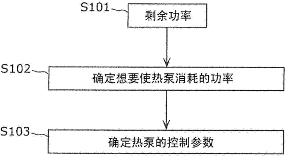
[0070] first, figure 1 It is a flowchart showing the outline of processing in the heat pump hot water supply system according to Embodiment 1 of the present invention.

[0071] Such as figure 1 As shown, the heat pump hot water supply system according to Embodiment 1 of the present invention first acq...

Embodiment approach 2

[0154] Below, refer to Figure 17 The operation of the heat pump hot water supply system according to Embodiment 2 of the present invention will be described. here, Figure 17 yes means Figure 10 Flowchart of another embodiment of . In addition, the detailed description of the points common to Embodiment 1 will be omitted, and the description will focus on the content unique to Embodiment 2. FIG.

[0155] Figure 17 The flow chart shown is similar to that except step S1205 is omitted. Figure 10same. That is, the information acquisition unit 209a of Embodiment 2 does not need to acquire the heat in the tank from the heat pump control unit 211 in step S1203. In addition, the operation control unit 209c of Embodiment 2 does not need to determine whether the second and third conditions are satisfied, and when the surplus power history satisfies the first condition (S1204: Yes), calculates the power consumption command value (S1206), When the power history does not satisfy...


PUM


Abstract

An operating method for a heat pump includes: a power generator; an information acquisition step for acquiring, per unit of time, the power generated by the power generator, the load power consumed by a power load, and the surplus power, which is the difference between the generated power and the load power; and an operation control step for controlling the operation of the heat pump. Therein, the operation control step involves increasing / decreasing the power consumed by the heat pump for generating heat, according to the increases / decreases in the surplus power per unit of time, when a state where the surplus power is equal to or greater than a pre-set threshold meets a first condition continuing for a prescribed interval leading up to the present.

Description

technical field [0001] The present invention relates to a heat pump system including a power generating device such as a solar power generating device and power consuming equipment such as a heat pump. Background technique [0002] Power generation devices such as solar power generation and wind power generation are devices for the purpose of generating energy. For example, solar power generation is a natural energy power generation device that converts the energy of sunlight into electricity and supplies it to households, and the power generated always fluctuates according to changes in weather or meteorological conditions. [0003] The heat pump hot water supply device is a device that absorbs heat from the atmosphere, compresses and heats the refrigerant using electricity, and forms hot water from water through a heat exchanger. Compared with conventional heater-type electric water heaters, it is an energy-saving hot water supply. device. [0004] A heat pump hot water ...

Claims


Application Information

Patent Timeline
Patent Type & Authority Applications(China)
IPC IPC(8): F24H1/00
CPCY02B30/762Y02B70/3275F24H1/00Y02E10/563H02J3/383H02J3/386Y04S20/222Y04S20/244F24D11/002Y02E10/763F25B49/00F24D2200/12H02J3/387Y02B70/3225H02J3/14F25B30/00F25B27/002F24D19/1039F24D2200/02H02J2310/14H02J2300/30H02J2300/28H02J2300/24H02J3/381Y02B30/70Y02B70/30Y02E10/56Y02E10/76Y04S20/242F24H15/144F24H15/254F24H15/375F24H15/215F24H15/164F24H15/421
Inventor 林田岳
Owner PANASONIC CORP
Why Eureka
Try Eureka