Method and device for producing a highly selectively absorbing coating on a solar absorber component, and solar absorber having such a coating

A solar energy absorption and absorption film technology, applied in solar thermal power generation, solar thermal devices, coatings, etc., can solve the problems of high equipment cost and lack of economy, and achieve the effect of high accuracy

Inactive Publication Date: 2013-02-13
ODB TEC
View PDF5 Cites 2 Cited by
  • Summary
  • Abstract
  • Description
  • Claims
  • Application Information

AI Technical Summary

Problems solved by technology

[0007] However, this approach also has disadvantages: the film thickness, which must be precisely set in order to absorb the visible spectrum, can only be achieved if the environmental conditions are kept precisely and constant, i.e. constant temperature, constant pressure and constant electrolyte concentration
However, the equipment required for this method is very expensive, and the expensive process is not economical to produce on an industrial scale for absorber tubes of several meters in length or, more generally, for flat plate products.

Method used


Image

  • Method and device for producing a highly selectively absorbing coating on a solar absorber component, and solar absorber having such a coating
  • Method and device for producing a highly selectively absorbing coating on a solar absorber component, and solar absorber having such a coating
  • Method and device for producing a highly selectively absorbing coating on a solar absorber component, and solar absorber having such a coating

Examples


Embodiment Construction

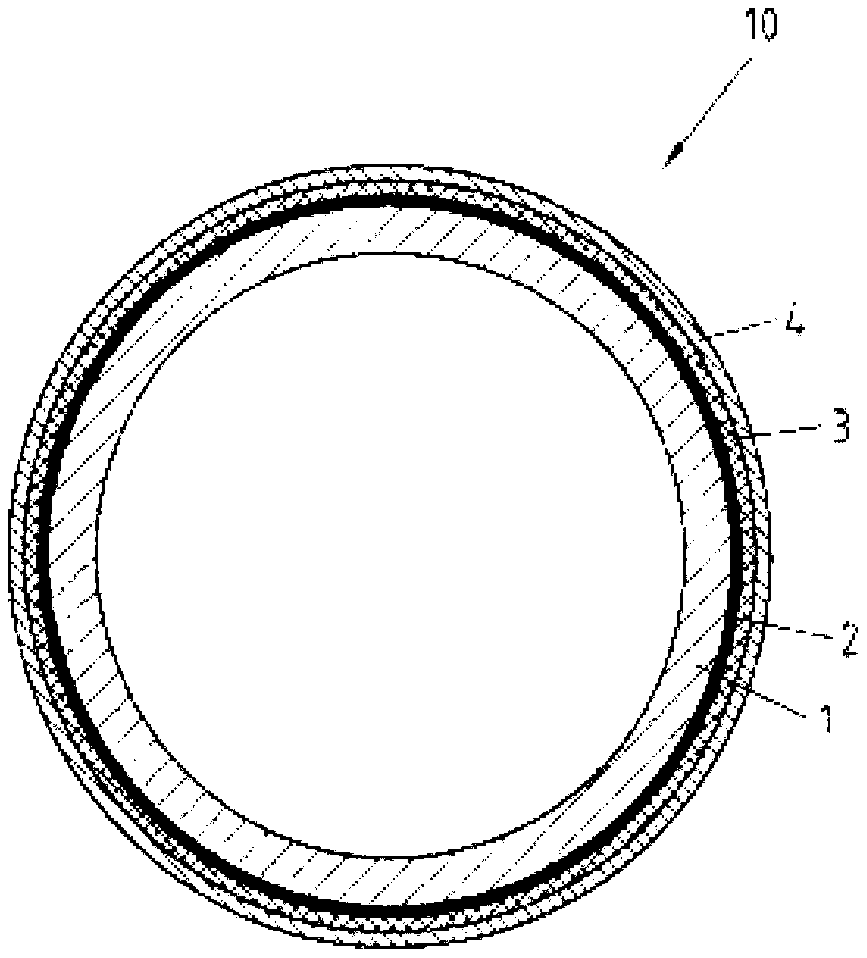
[0045] figure 1 A cross-section of an absorber tube 10 with a selectively absorbing film for a bowl-shaped trough collector is depicted. Here, in order to achieve visual clarity, the thickness of each film and the thickness of the substrate material are not marked.

[0046] figure 1 The absorption pipe 10 in the present invention comprises a steel pipe 1, and the steel pipe 1 is provided with a layer of film 2 which helps to increase the adhesion on its outer surface. Here, preferably, the film 2 is an aluminum or steel film, wherein the film 2 is preferably deposited on the steel pipe surface by electrolysis. Since this adhesion-promoting film 2 is completely free of pores, it is preferred here that the electrolytically deposited film has a minimum thickness of 8-10 microns.

[0047] However, for some steel pipes with poor surface quality, the steel pipe 1 will have pores on its surface. In this case, the following scheme is meaningful: First, a metal film (such as nickel)...


PUM

PropertyMeasurementUnit
thicknessaaaaaaaaaa
thicknessaaaaaaaaaa
thicknessaaaaaaaaaa

Abstract

The invention relates to a method for producing a selectively absorbing coating (3) on a solar absorber component (10), comprising the following steps: providing a substrate (1) having a metal surface, determining the inner surface of the metal surface, determining the charge quantity per unit area required for generating the absorbing coating in accordance with the inner surface; ; electrolytically generating the absorbing coating (3) in a first step by direct-current anodizing the metal surface of the substrate (1), forming a porous oxide coating, and in a second step by alternating-current pigmenting the pores of the oxide coating, direct-current anodizing and alternating-current pigmenting take place until the charge quantity per unit area determined for each step from the inner surface is reached, wherein the ratio between the charge quantity per unit area rouA for the direct-current anodizing and the charge quantity per unit area roup for the alternating-current pigmenting rouA/rouP = 0.65 to 0.8. The invention further relates to a solar absorbing component (10) produced according to said method.

Description

technical field [0001] The present invention relates to a method for preparing a selectively absorbing film on a solar absorbing module and a solar absorbing module prepared according to this method. Background technique [0002] With the increasingly tight supply of fossil energy, the utilization of solar energy is becoming more and more important in industrialized countries. [0003] On the one hand, the energy of solar radiation can be directly converted into electrical energy through photovoltaic technology. On the other hand, solar energy can also be used in traditional solar thermal flat panel collectors and solar thermal power plants (concentrating solar power plants, CSP). In such a solar thermal power plant, the focusing reflector surface concentrates and heats the sunlight that strikes the absorbing surface, which is in contact with a heat-conducting medium on its opposite side, for example heat-conducting oil or heated steam. The further heated vapors in the abs...

Claims


Application Information

Patent Timeline
Patent Type & Authority Applications(China)
IPC IPC(8): F24J2/48C25D11/22C25D7/00
CPCC25D7/08Y02E10/46Y02E10/40F24J2/4652F24J2/487C25D11/22C25D7/00F24S70/25F24S70/30F24S70/225
Inventor 迪特尔·奥斯特曼
Owner ODB TEC
Why Eureka
Try Eureka