Motor-driven steam mop

A steam and electric technology, applied to manual floor scrubbing machines, carpet cleaning, household appliances, etc., can solve the problems of low efficiency, low machine power, high motor speed, etc., to reduce heavy housework and reduce volume , the effect of flexible speed

Active Publication Date: 2013-02-20
GUANGDONG XINBAO ELECTRICAL APPLIANCES HLDG CO LTD
View PDF6 Cites 12 Cited by
  • Summary
  • Abstract
  • Description
  • Claims
  • Application Information

AI Technical Summary

Problems solved by technology

[0002] In the housework of housewives, mopping the floor is a time-consuming and labor-intensive task. However, this type of power tool on the market is designed for larger commercial places, and is not suitable for home use due to its bulkiness and size.
In addition, there are individual published patents, which are inefficient and impractical. For example, the utility model patent disclosed by Patent No. 200720047253.X discloses a vibrating steam floor mop. Part of the kinetic energy generated by the machine is absorbed by the mop, and the cleaning efficiency is low. If the power is increased, the machine will vibrate greatly, making it difficult for the user to operate; the motor 6 is arranged on the mop head 2, so the mop head 2 is relatively high, and it is used as a household , many places will not be able to be cleaned; the high voltage reaches the mop head 2, which is very close to the ground, and there is water and water vapor in the mop head 2, so there is a risk of electric shock; the frequency of the vibrating mop is high, the motor 6 rotates at a high speed, and the noise Big

Method used


Image

  • Motor-driven steam mop
  • Motor-driven steam mop
  • Motor-driven steam mop

Examples


Embodiment

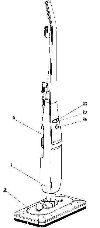
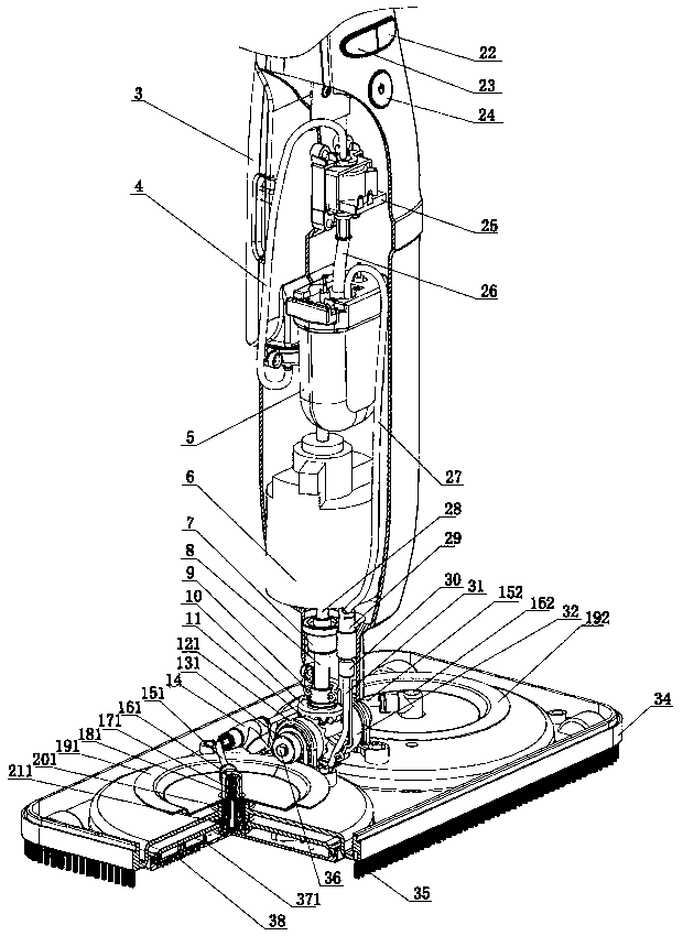
[0031] The structure diagram of the present invention is as figure 1 , 2, 3, and 4, the electric steam mop of the present invention includes a handle (1), a mop head (2) mounted on the lower part of the handle (1), a mopping mechanism mounted on the mop head (2), An electric system that drives the movement of the mopping mechanism and a steam system that delivers steam to the mopping mechanism, wherein the electric system is installed on the handle (1), and the electric system is connected to the mopping mechanism through a transmission mechanism.

[0032] The above-mentioned mop head 2 includes a connector 32 and a mop head seat 34. The connector 32 can be a part that can be detached from the handle 1, or can be a part of the handle 1 that cannot be detached from the handle 1. In order to make the floor mop easier to clean, the present invention preferentially makes the connecting head 32 detachable from the handle 1. In this way, after the floor mop is removed, there is no ...

Embodiment 2

[0051] like Figure 7 As shown, in this embodiment, the bevel gear pair in the connecting head 32 of the first embodiment is replaced by a worm gear transmission mechanism, the worm 47 replaces the input shaft 8 and the driving bevel gear 10, the worm wheel 45 replaces the driven bevel gear 11, and the worm 47 coincides with the connecting shaft 44 of the connecting head 32, the worm wheel 45 is connected with the output shaft 36, and the output shaft 36 coincides with the rotating shaft 33 of the connecting head 32. After the handle 1 is connected to the connector 32 of the mop head 2, the motor shaft 28 of the motor 6 is connected to the male shaft connector 42 at the shaft end of the worm 47 through the female shaft connector 7 at the shaft end. Obviously, the two shafts of the bevel gear pair in Embodiment 1 intersect with an included angle of 90°, while the shaft of the worm wheel 45 in Embodiment 2 does not intersect with the worm shaft (that is, the output shaft 36 ), b...

Embodiment 3

[0054] like Figure 9 , this embodiment uses a pair of friction wheels to replace the bevel gear pair in the connecting head 32 of the first embodiment. This embodiment adopts conical friction wheel transmission, and the friction wheel transmission needs to apply pressure between the friction wheels. A pressure spring 50 is arranged between the active conical friction wheel 48 and the bearing. Under the effect of the pressure spring 50, the active conical friction wheel 48 and the driven conical friction wheel 49 are compressed, and the two conical friction wheels Appropriate frictional force has been produced between them, and when the active conical friction wheel 48 rotates, it drives the driven conical friction wheel 49 to rotate, and its effect is consistent with that of the bevel gear pair in Embodiment 1, and the direction of transmission is also changed. And also can change the transmission speed according to need. The connecting head 32 of this embodiment is driven b...


PUM


Abstract

The invention relates to a motor-driven steam mop which comprises a handle (1), a mop head (2) assembled on the lower portion of the handle (1), a floor mopping mechanism arranged on the mop head (2), a motor-driven system driving the floor mopping mechanism to move and a steam system delivering the steam to the floor mopping mechanism. The motor-driven system is installed on the handle and is connected with the floor mopping mechanism through a transmission mechanism. The motor-driven steam mop adopts a motor structure arranged on the handle, drives the floor mopping mechanism on the mop head to move through the transmission mechanism in the connector, reduces size of the mop head, and especially reduces height of the mop head, so that the mop becomes small and exquisite, is suitable for being used by houses, simultaneously enables electrified parts to be far away from water and steam and better separates water from high voltage electricity. In addition, the mop head is not electrified and can be placed in water to be washed after being disassembled, thereby being safe and convenient. The motor-driven steam mop replaces manpower with electric power and is high in efficiency, safe and reliable.

Description

technical field [0001] The invention is an electric steam mop, which belongs to the transformation technology of the electric steam mop. Background technique [0002] In the housework of housewives, mopping the floor is a time-consuming and labor-intensive task. However, such power tools on the market are designed for larger commercial places, and are not suitable for home use due to their heavy weight and large size. In addition, there are individual published patents, which are inefficient and impractical. For example, the utility model patent disclosed by Patent No. 200720047253.X discloses a vibrating steam floor mop. Part of the kinetic energy generated by the machine is absorbed by the mop, and the cleaning efficiency is low. If the power is increased, the machine will vibrate greatly, making it difficult for the user to operate; the motor 6 is arranged on the mop head 2, so the mop head 2 is relatively high, and it is used as a household , many places will not be abl...

Claims


Application Information

Patent Timeline
Patent Type & Authority Applications(China)
IPC IPC(8): A47L11/26A47L11/40
CPCA47L11/4038A47L11/34A47L11/26A47L11/4088A47L11/40
Inventor 郭建刚刘会胡细辉
Owner GUANGDONG XINBAO ELECTRICAL APPLIANCES HLDG CO LTD
Why Eureka
Try Eureka