
Engine EGR (exhaust gas recirculation) system

A recirculation system and exhaust gas recirculation technology, applied in exhaust gas recirculation, engine components, combustion engines, etc., can solve the problem of reducing the durability of plastic intake manifolds, reducing the temperature of engine circulating water, and prolonging engine warm-up time, etc. problems, to achieve the effect of shortening the warm-up time, increasing the intake air volume, and reducing the risk of failure

Active Publication Date: 2013-02-20
GREAT WALL MOTOR CO LTD
View PDF6 Cites 5 Cited by
  • Summary
  • Abstract
  • Description
  • Claims
  • Application Information

AI Technical Summary

Problems solved by technology

However, the existing engine exhaust gas recirculation (EGR) system has defects in the following aspects: first, the tube and shell cooler used is large in size, which is not conducive to the layout of the engine; second, the cooling capacity changes with the engine speed, resulting in sometimes Excessive cooling of the EGR system and the increase of supercooled exhaust gas condensate will cause serious carbon deposits in the EGR valve, and even blockage. Sometimes the cooling of the EGR system is insufficient. In the small circulation state, the circulating water of the engine enters the EGR system, resulting in a decrease in the temperature of the circulating water of the engine and prolonging the engine warm-up time; Fourth, there is no cooling water channel on the EGR valve seat, and the EGR valve seat is deformed under the impact of high thermal energy. To reduce the risk of failure, most EGR valve seats are made of stainless steel, which increases the cost; fifthly, in order to avoid the influence of engine exhaust gas condensate on EGR, the EGR outlet temperature is relatively high, resulting in the mixing of high-temperature exhaust gas and fresh air, so that the total intake of the engine Reduced gas volume not only affects engine performance, but also reduces durability of plastic intake manifold

Method used


Image

  • Engine EGR (exhaust gas recirculation) system
  • Engine EGR (exhaust gas recirculation) system
  • Engine EGR (exhaust gas recirculation) system

Examples


Embodiment Construction

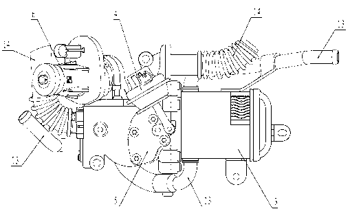
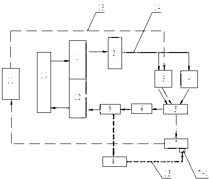
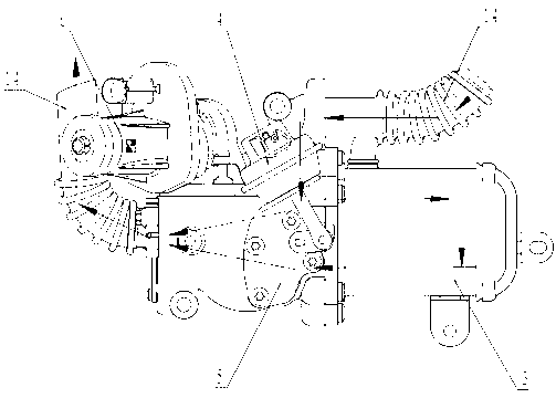
[0020] See Figure 1, figure 2 , the present invention includes a cooling water circulation mechanism and an exhaust gas recirculation mechanism, the cooling water circulation mechanism communicates with the vehicle radiator 11, the cooling water circulation mechanism adjusts the temperature of the recirculated exhaust gas under the control of the engine ECU 8, and the exhaust gas recirculation mechanism It is arranged between the engine exhaust manifold 2 and the exhaust gas intake channel 12 of the engine cylinder head. The present invention uses the electronic water pump 7 to control the cooling water flow rate of the electronic water pump 7 through the signal sent by the temperature sensor 9 to the engine ECU 8 (or the nitrogen oxide content detected by the emission detection system), so as to realize the control of the cooling capacity of the EGR system , when the recirculation exhaust gas temperature is higher than the actual demand temperature, adjust the electronic wat...


PUM


Abstract

The invention discloses an engine EGR (exhaust gas recirculation) system for lowering the content of NOx in emissions of a diesel engine vehicle. The engine EGR system comprises a cooling water circulation mechanism and an exhaust gas recirculation mechanism, wherein the cooling water circulation mechanism is communicated with a whole vehicle radiator, and regulates the temperature of recirculation exhaust gas under the control of an ECU (electronic control unit) of the vehicle; and an EGR mechanism is configured between an engine exhaust manifold and an engine cylinder head exhaust gas inlet channel. The engine EGR system disclosed by the invention overcomes the defects of the existing EGR system, and can reduce the NOx content in tail gas of the vehicle greatly, meet the requirements of vehicle emission standards and improve the comprehensive performance of the engine.

Description

technical field [0001] The invention relates to an exhaust gas recirculation system of an engine, in particular to an exhaust gas recirculation system of a vehicle-mounted diesel engine, and belongs to the technical field of combustion engines. Background technique [0002] For cars equipped with diesel engines, due to the high air-fuel ratio of the engine, the fuel burns under high-temperature and oxygen-enriched conditions, resulting in a large amount of NOx in the exhaust gas. NOx is a substance harmful to human health, and its content is strictly limited in automobile emission standards. Therefore, treating NOx in converted exhaust gas is one of the main tasks to improve the emission performance of diesel engines. At present, the reduction of NOx content in engine emissions is generally achieved through engine exhaust gas recirculation (EGR) and conversion and absorption of after-treatment devices. [0003] The engine exhaust gas recirculation (EGR) device is adopted by...

Claims


Application Information

Patent Timeline
IPC IPC(8): F02M25/07F02M26/14F02M26/21F02M26/23F02M26/28F02M26/33
CPCY02T10/121Y02T10/12
Inventor 郝学信屈伟赵勇刘祖勤刘占强崔志强
Owner GREAT WALL MOTOR CO LTD
Learn More