Transmission mechanism of diaphragm of mechanical diaphragm metering pump

A diaphragm metering pump and transmission mechanism technology, applied in the direction of machines/engines, mechanical equipment, transmission devices, etc., can solve problems such as high cost, high maintenance cost, wear and tear, achieve a large competitive advantage, facilitate large gear transmission, and convert structures simple effect

Active Publication Date: 2013-02-20
ZHEJIANG AILIPU TECH
View PDF7 Cites 0 Cited by
  • Summary
  • Abstract
  • Description
  • Claims
  • Application Information

AI Technical Summary

Problems solved by technology

But it does have many disadvantages: 1. The machining accuracy of the centered crosshead mechanism is very high, otherwise it will cause vibration-accelerated wear. At the same time, it has extremely high requirements for the hardness and toughness of the material used, and quenching and tempering treatment is required. It inevitably makes its cost very high; 2. The assembly has very high requirements, which requires the assembly personnel to have extremely high requirements in terms of technology and experience; 3. The maintenance cost is very high. Once the mechanism is worn out and scrapped, many maintenance companies basically use direct replacement

Method used


Image

  • Transmission mechanism of diaphragm of mechanical diaphragm metering pump

Examples


Embodiment Construction

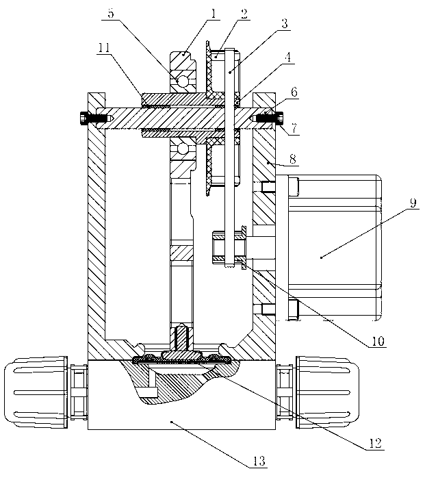
[0013] Below in conjunction with accompanying drawing, the present invention will be further described:

[0014] A diaphragm transmission mechanism of a mechanical diaphragm metering pump, including a pump head 13, a diaphragm 12, a connecting rod 1, a base 8 and a motor 9 that cooperate with each other, the diaphragm 12 isolates the pump head 13 into a closed cavity, and the motor 9 passes through a screw Fixed on one side of the base 8, a pinion 10 is set on the output shaft of the motor 9 for interference, and the pinion 10 is connected with the large gear 2 on the top of the base 8 through a synchronous belt 3; The two ends are fixed on the base 8 by bolts 7, and the eccentric sleeve 4 is arranged on the pin shaft 6, and both sides of the eccentric sleeve 4 are rotated and matched with the pin shaft 6 arranged on the top of the base through the needle bearing 11; the right end of the eccentric sleeve 4 is set as Concentric structure, the left end of the eccentric sleeve 4 ...


PUM


Abstract

The invention relates to a mechanical diaphragm metering pump, in particular to a transmission mechanism of a diaphragm of a mechanical diaphragm metering pump. The transmission mechanism is characterized in that a pinion is arranged on an output shaft of a motor in an interference manner, and is connected with a gear wheel by a synchronous belt, and the gear wheel is arranged on the top of a base; a hinge pin is arranged on the top of the base, an eccentric sleeve is fittingly arranged on the hinge pin, and the gear wheel is in interference fit with the eccentric sleeve; and a bearing is arranged on the eccentric sleeve and positioned on one side of the gear wheel, a connecting rod is arranged at the outer edge of the bearing in an interference manner, the diaphragm is arranged at a free end of the connecting rod, and the gear wheel drives the connecting rod to move via the eccentric sleeve. The end of the eccentric sleeve connected with the gear wheel is of a concentric structure, so that transmission of the gear wheel is facilitated; and the end of the eccentric sleeve connected with the connecting rod is of an eccentric structure, so that the connecting rod can be driven to reciprocate when the eccentric sleeve moves. Besides, a structure for converting rotational movement into linear movement is quite simple, so that production, assembly and maintenance costs are greatly reduced, and the mechanical diaphragm metering pump is high in competitive strength in markets.

Description

technical field [0001] The invention relates to a mechanical diaphragm metering pump, in particular to a diaphragm transmission mechanism of a mechanical diaphragm metering pump. Background technique [0002] As we all know, in the mechanical diaphragm metering pump, the rotary motion of the motor is almost always converted into reciprocating linear motion through a conversion mechanism. At present, domestic manufacturers basically use cam-link technology. Due to the existence of processing or assembly tolerances, no matter how precise processing equipment and high assembly level you use, it will have a certain deviation from the ideal benchmark. At present, the commonly used scheme in China is to set up a crosshead automatic guiding and centering mechanism at the connecting part of the connecting rod and the diaphragm to solve the problem of automatic centering between the radial center of the cam and the center of the diaphragm. This type of device has become very mature ...

Claims


Application Information

Patent Timeline
Patent Type & Authority Applications(China)
IPC IPC(8): F04B53/00F04B13/00F04B43/02F16H37/12F16H57/035
Inventor 罗献尧杨华锋韩硕
Owner ZHEJIANG AILIPU TECH
Why Eureka
Try Eureka