Method for designing oscillating tooth transmission speed reducer

A technology of movable tooth transmission and design method, which is applied in instruments, calculations, special data processing applications, etc., can solve the problems of inability to meet the needs of industrialization, long development cycle of reducers, etc., to shorten development time, reduce production costs, and make reasonable Effects of Tolerance Assignment

Active Publication Date: 2013-02-20
WENZHOU UNIVERSITY
View PDF1 Cites 2 Cited by
  • Summary
  • Abstract
  • Description
  • Claims
  • Application Information

AI Technical Summary

Problems solved by technology

For engineers with many years of experience, this process takes several years or even longer to complete, and the cost during the period is a huge amount, which leads to a rather long design and development cycle of the reducer, which is increasingly unable to meet the needs of industrialization. need

Method used


Image

  • Method for designing oscillating tooth transmission speed reducer
  • Method for designing oscillating tooth transmission speed reducer
  • Method for designing oscillating tooth transmission speed reducer

Examples


Embodiment Construction

[0019] The present invention will be described in further detail below in combination with specific embodiments.

[0020] In this embodiment, a roller movable tooth transmission reducer is taken as an example for illustration, and the design process is realized based on ADAMS dynamic simulation analysis software.

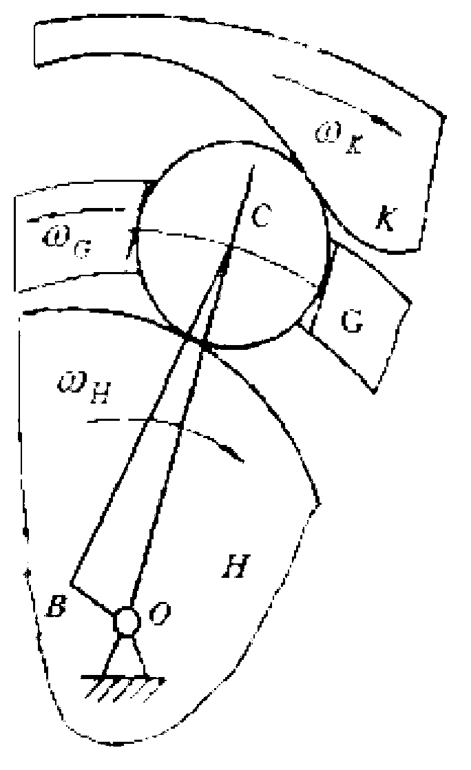
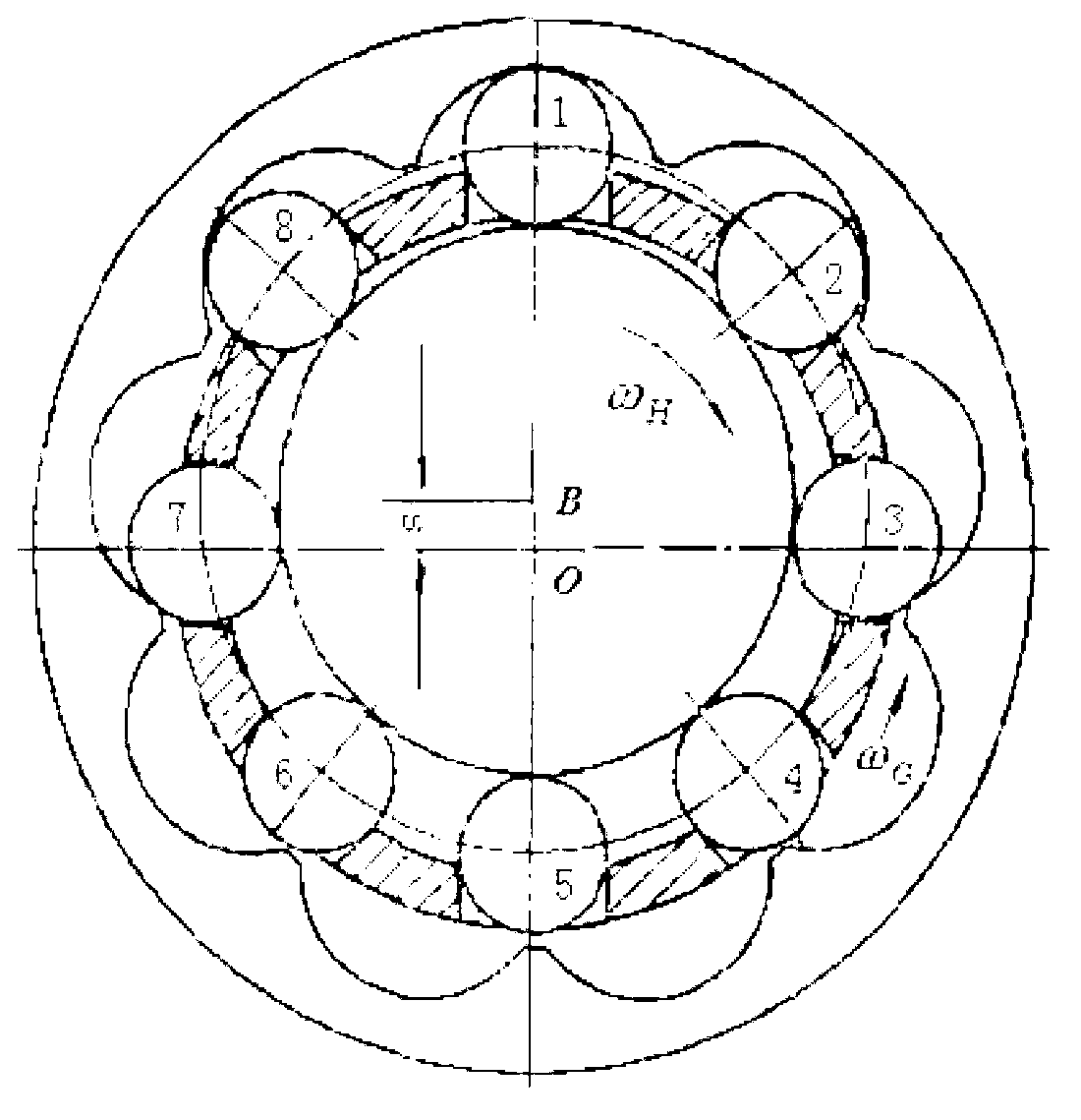
[0021] The structure of the roller movable tooth transmission reducer is as follows: Figure 1-2 As shown, the roller movable tooth transmission consists of three basic components: the center wheel K, the movable gear G and the shock wave device H. The geometric center of the shock wave H is B, and the rotation center is 0. The movable gear G is made up of a group of roller movable teeth (bearing rollers) in the movable rack and its radial guide groove. If the center wheel is fixedly connected with the base, the output of the movement is finally completed by the movable gear frame, and the connection between the movable gear frame and the output shaft can be integ...


PUM


Abstract

The invention provides a method for designing an oscillating tooth transmission speed reducer. The method includes establishing a basic model of the oscillating tooth transmission speed reducer; updating the basic model, establishing a virtual prototype, obtaining load, displacement, speed and accelerated speed of each part of the oscillating tooth transmission speed reducer, acquiring an ideal value of each critical parameter by a reverse engineering method, redefining common differences of the critical parameters, and completing the design of an engineering drawing of the oscillating tooth transmission speed reducer according to basic values and the common differences of the critical parameters. According to the method for designing the oscillating tooth transmission speed reducer, under the condition that the critical functions of transmission efficiency, return difference and the like of the speed reducer are guaranteed, the developing time can be substantially shortened, the analysis and the drawing are combined, so that a virtual prototype technology can complete integral design of analysis, computation, plotting and production by really combining the actual production, the common difference distribution is reasonable, the speed reducer function is achieved within a maximum common difference range, and the production cost can be greatly reduced.

Description

technical field [0001] The invention belongs to the field of reducers, and in particular relates to a design method of a movable tooth transmission reducer. Background technique [0002] The reducer is a power transmission mechanism that uses the speed converter of the gear to reduce the number of revolutions of the motor (motor) to the desired number of revolutions and obtain a larger torque mechanism. Among the mechanisms currently used to transmit power and motion, reducers are used in a wide range of applications. It can be seen in almost all kinds of mechanical transmission systems, from ships, automobiles, locomotives, heavy machinery used in construction, processing machinery and automated production equipment used in the machinery industry, to common in daily life. Appliances, watches and more. Its application ranges from the transmission of large power to small loads. The precise angle transmission can be seen in the application of the reducer, and in industrial a...

Claims


Application Information

Patent Timeline
Patent Type & Authority Applications(China)
IPC IPC(8): G06F17/50
Inventor 李峰平周余庆郑云马光
Owner WENZHOU UNIVERSITY
Why Eureka
Try Eureka