Electronic device applied in EUV (Extreme Ultraviolet) vacuum environment

A vacuum environment and electronics technology, applied in the field of semiconductors, can solve problems such as pollution of electronic devices, achieve effective work, ensure transmission efficiency, and reduce pollution

Active Publication Date: 2015-04-29
ZHONGKE JINGYUAN ELECTRON LTD
View PDF2 Cites 0 Cited by
  • Summary
  • Abstract
  • Description
  • Claims
  • Application Information

AI Technical Summary

Problems solved by technology

[0006] The purpose of the embodiments of the present invention is to provide an electronic device used in an EUV vacuum environment, which solves the technical problem of pollution of the electronic device in the vacuum environment in the prior art, realizes the cleaning of the vacuum chamber, and improves EUV Light transfer efficiency, technical effect of improving performance and lifetime of optical components

Method used


Image

  • Electronic device applied in EUV (Extreme Ultraviolet) vacuum environment
  • Electronic device applied in EUV (Extreme Ultraviolet) vacuum environment
  • Electronic device applied in EUV (Extreme Ultraviolet) vacuum environment

Examples


Embodiment 1

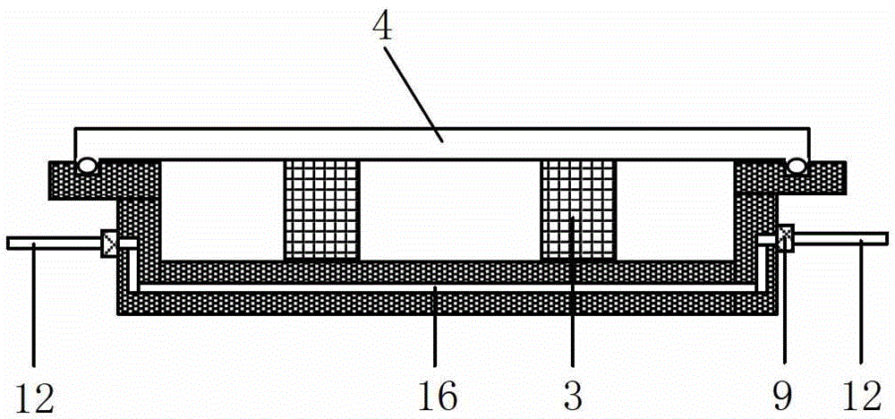
[0046] [Example 1] The embodiment of the liquid temperature control method is as follows image 3 Shown:

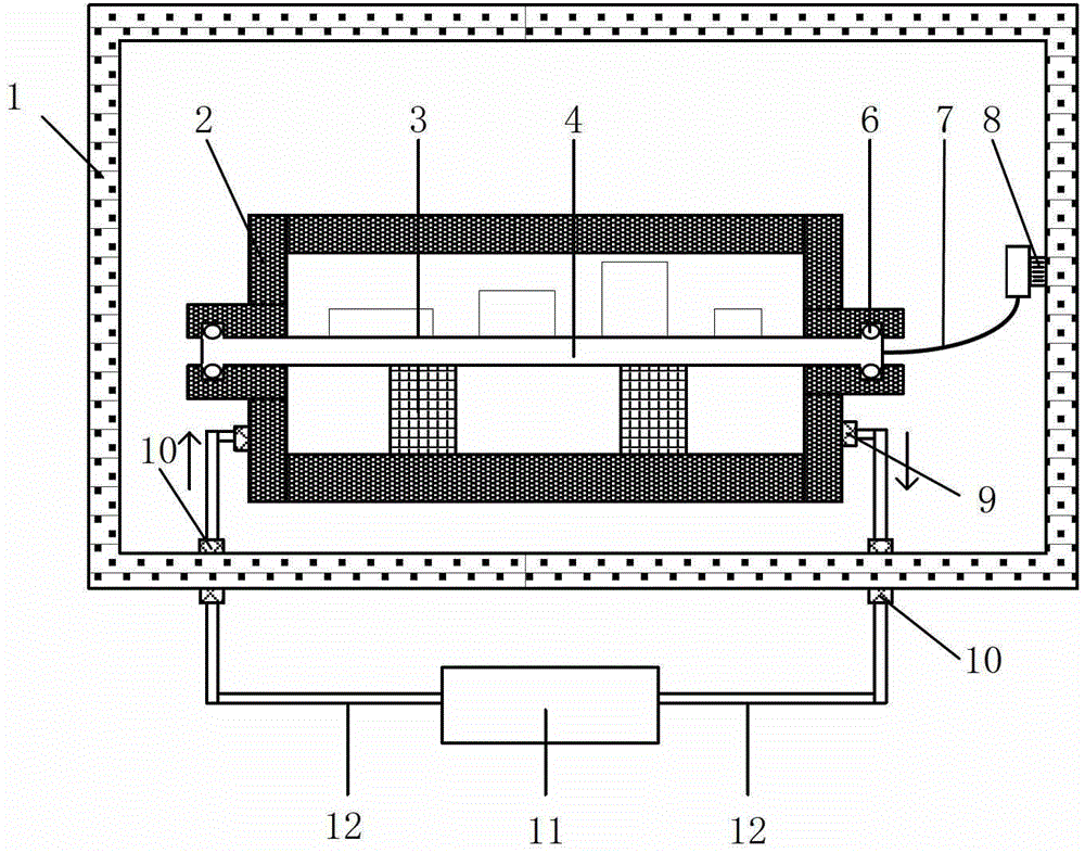
[0047] The temperature control liquid enters the second temperature control pipeline 16 in the sealed casing 2 through the first temperature control pipeline 12, and there is a first temperature control connector 9 between the first temperature control pipeline 12 and the second temperature control pipeline 16, so that the sealing Shell 2 maintains a lower temperature. The heat conduction element 3 transfers the heat of the electronic system 4 to the sealed casing 2, and the temperature control fluid takes the heat away from the sealed casing 2 and brings it to the power temperature control device 11 for processing, thereby achieving the control of the electronic system 4. effect of effective heat dissipation.

Embodiment 2

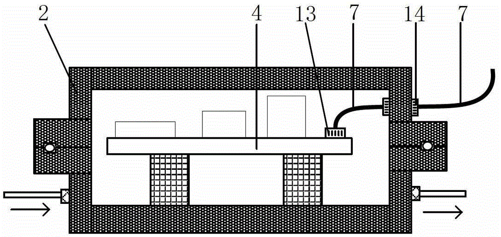
[0048] [Example 2] The embodiment of the gaseous temperature control method is as follows Figure 4 Shown:

[0049] The temperature-controlled gas enters the sealed housing 2 through the second cooling pipeline 16 in the sealed housing 2, and there is a first temperature-controlled connector 9 between the first temperature-controlled pipeline 12 and the second temperature-controlled pipeline 16 of the sealed housing 2 , the first temperature-controlled connector 9 ensures the tightness of the sealed casing 2, the temperature-controlled gas takes away the heat from the surface of the electronic system 4, and at the same time takes away the pollutants in the sealed casing 2, and the temperature-controlled gas enters the Processing is performed in the power temperature control device 11 to clean the temperature-controlled gas, and at the same time further cool / heat the temperature-controlled gas, so as to effectively control the temperature of the electronic system 4 . That is t...

Embodiment 3

[0050] [Example 3] Examples of solid-state temperature control methods Figure 5 Shown:

[0051] This method is adopted when the heat generated by the electronic system 4 is not large. The heat conduction member 3 is made of a semiconductor temperature control material, which can absorb the heat generated by the electronic system 4 and transfer it to the sealed casing 4 connected to it, so as to achieve The electronic system 4 performs effective temperature control.

[0052] For the embodiment of the present invention, the sealed casing 2, the heat conducting element 3, and the connecting element are all made of low outgassing materials.

[0053] The above-mentioned technical solutions in the embodiments of the present application have at least the following technical effects or advantages:

[0054] An electronic device used in an EUV vacuum environment provided by an embodiment of the present invention puts the electronic system into a sealed casing so that the pollutants e...


PUM


Abstract

The invention discloses an electronic device applied in an EUV (Extreme Ultraviolet) vacuum environment. The electronic device is located in a vacuum cavity, wherein the vacuum cavity is used for providing a EUV light survival environment, and the electronic device comprises an electronic system, wherein the electronic system is located in the vacuum cavity, and the electronic system is used for realizing the electronic functions of a EUV photoetching system; and a sealing shell, wherein the sealing shell is located in the vacuum cavity, and the sealing shell is used for sealing the electronic system and preventing pollutants formed by the electronic system from entering the vacuum cavity. The device is capable of effectively preventing the pollutants formed by the electronic system from entering the vacuum cavity, reducing pollution on the EUV vacuum environment and ensuring the transmission efficiency of EUV light; and a temperature controller and a heat conduction element are used for controlling the temperature of the electronic system in the sealing shell to ensure the normal work of the electronic system.

Description

technical field [0001] The invention relates to the technical field of semiconductors, in particular to an electronic device in an EUV vacuum environment. Background technique [0002] Due to the increasingly high integration requirements of the semiconductor industry for integrated circuits (IC, Integrated Circuits), traditional visible light or ultraviolet lithography machines can no longer meet the development needs of the industry, and the market needs lithography equipment with better performance to maintain the entire industry. rapid development momentum. It is well known that the lithographic resolution is inversely proportional to the numerical aperture of the projection objective and directly proportional to the exposure wavelength. Therefore, in order to improve the resolution of lithography, the next generation of lithography machines will use shorter wavelength extreme ultraviolet light (EUV, extreme ultra violet) to replace the existing visible light and ultrav...

Claims


Application Information

Patent Timeline
Patent Type & Authority Patents(China)
IPC IPC(8): G03F7/20
Inventor 宗明成孙裕文徐天伟黄有为
Owner ZHONGKE JINGYUAN ELECTRON LTD
Why Eureka
Try Eureka