Small high-low temperature tester

A high and low temperature test, high and low temperature test chamber technology, applied in the direction of laboratory appliances, heating or cooling equipment, shell or chamber, etc., can solve the problem of complex structure of high and low temperature test chamber, difficulty in meeting humidity test, complicated operation process, etc. problems, to achieve the effect of convenient structural design and layout, simple structure, simple and convenient operation

Active Publication Date: 2013-02-27
NANJING UNIV OF AERONAUTICS & ASTRONAUTICS
View PDF2 Cites 9 Cited by
  • Summary
  • Abstract
  • Description
  • Claims
  • Application Information

AI Technical Summary

Problems solved by technology

[0002] At present, most of the high and low temperature test chambers, whether using compressor refrigeration or liquid nitrogen refrigeration, use large and closed test chambers. If there is a transmission shaft input, the chamber will be damaged. The structure of the body is more complicated. In some high and low temperature tests that require torque and rotation input, considering the working environment of the motor, the motor is generally placed outside the high and low temperature box, and the transmission shaft passes through the wall of the high and low temperature box to transfer the torque and rotating speed are transmitted into the test chamber and transmitted to the test piece. Because of the input of the transmission shaft, it is necessary to design the sealing structure at the input of the transmission shaft of the cabinet, which makes the structure of the high and low temperature test chamber complex and greatly increases the production cost; if The precision of the test is very high, and the influence of friction caused by the sealing structure must also be considered, which makes the design work more difficult; the control system is also relatively complicated, and the operation process is complicated, which greatly increases the production cost; During the low temperature test, the dehumidification effect will be limited to a certain extent, and it is difficult to meet the strict requirements of the humidity test.

Method used


Image

  • Small high-low temperature tester
  • Small high-low temperature tester
  • Small high-low temperature tester

Examples


Embodiment Construction

[0020] The present invention will be further described below in conjunction with the accompanying drawings, but the present invention is not limited to the scope of the embodiments.

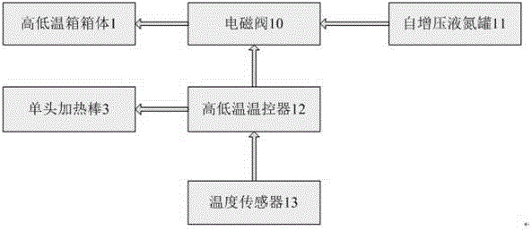
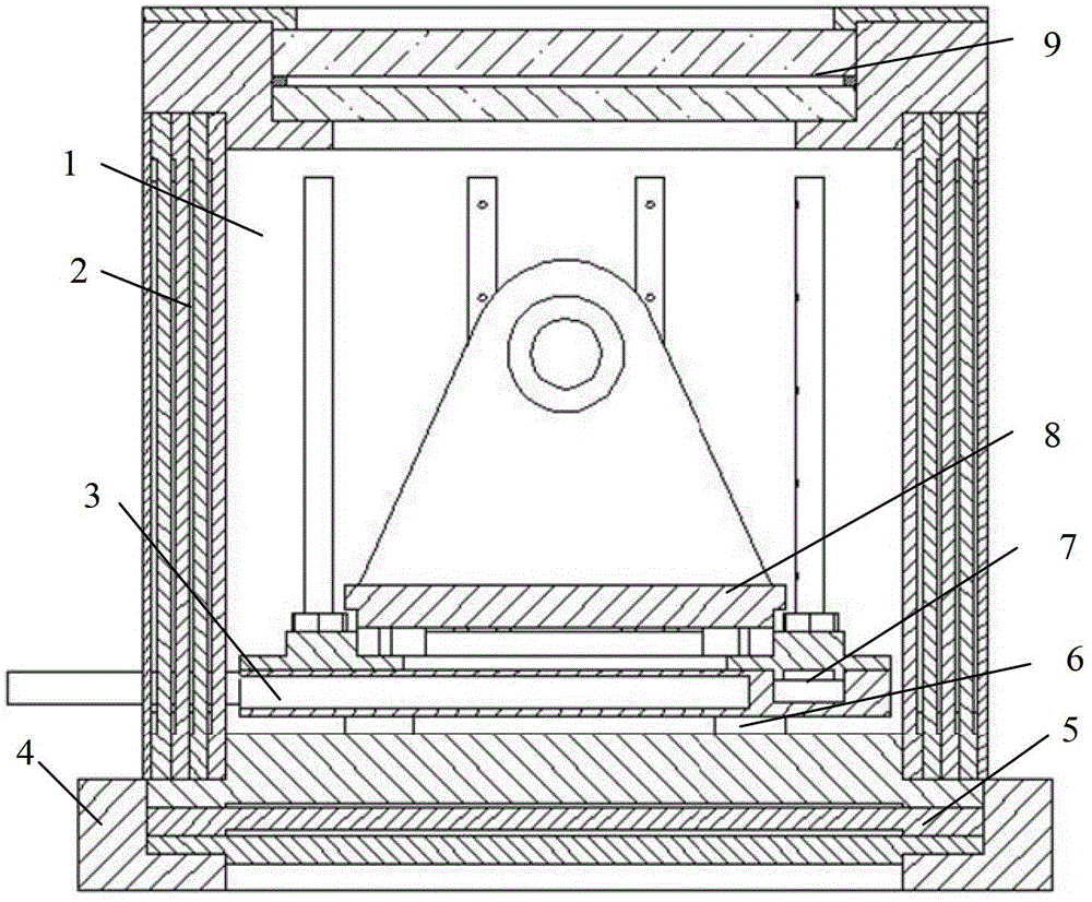
[0021] Referring to the accompanying drawings, the high and low temperature test chamber includes a high and low temperature test chamber body 1, a temperature sensor 13, a single-head heating rod 3, a solenoid valve 10, a self-pressurized liquid nitrogen tank 11 and a high and low temperature thermostat 12. The high and low temperature test box body 1 includes a side insulation board 2 , a bottom insulation board 5 , a tempered glass cover 9 , a base 4 , a cooling and heating system stand 7 and a test piece mounting bracket 8 .

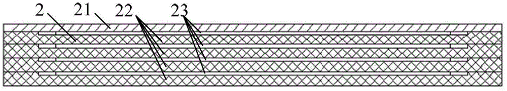
[0022] The side insulation board 2 is composed of four layers of epoxy boards 22 and one layer of stainless steel boards 21 stacked and fixed. A thin layer of air layer 23 is formed between the epoxy boards 22 and between the epoxy board 22 and the stainless steel board ...


PUM


Abstract

The invention discloses a small high-low temperature tester, which provides a high-low temperature environment for tests. The small high-low temperature tester comprises a high-low temperature test box, a temperature sensor, a single-headed heating rod, an electromagnetic valve, a self-pressurizing liquid nitrogen tank and a high-low temperature controller; the high-low temperature test box adopts the high-low temperature controller as a controller to control the single-headed heating rod and the electromagnetic valve to carry out heating and cooling processes; the high-low temperature test box adopts epoxy boards as thermal insulation layers, and when the difference between the temperatures inside and outside the high-low temperature test box is about 100 DEG C, the outside of the high-low temperature test box cannot be frosted. The size of the high-low temperature test box is small, the structure is simple, the small high-low temperature tester is practical and convenient, the temperature stability is good, the precision is higher, the temperature can be optionally set within a range from 60 DEG C below zero to 60 DEG C, and the small high-low temperature tester can satisfy part of currently known high-low temperature tests needing transmission shaft input.

Description

technical field [0001] The invention relates to a small high and low temperature test device, in particular to an open small high and low temperature test device with transmission shaft input. technical background [0002] At present, most of the high and low temperature test chambers, whether using compressor refrigeration or liquid nitrogen refrigeration, use large and closed test chambers. If there is a transmission shaft input, the chamber will be damaged. The structure of the body is more complicated. In some high and low temperature tests that require torque and rotation input, considering the working environment of the motor, the motor is generally placed outside the high and low temperature box, and the transmission shaft passes through the wall of the high and low temperature box to transfer the torque. and rotating speed are transmitted into the test chamber and transmitted to the test piece. Because of the input of the transmission shaft, it is necessary to design...

Claims


Application Information

Patent Timeline
Patent Type & Authority Applications(China)
IPC IPC(8): B01L1/00B01L7/00
Inventor 聂宏陈传志王小涛陈金宝李春颜文彧徐敏席佳胜杨健邓飞杨铭波
Owner NANJING UNIV OF AERONAUTICS & ASTRONAUTICS
Why Eureka
Try Eureka