
Welding device and method for superconducting lines

A welding device and superconducting wire technology, applied in the direction of electric heating devices, auxiliary devices, welding equipment, etc., can solve the problems of insufficient heating temperature, large dispersion of welding quality, overheating of welded parts, etc., and achieve high reliability.

Active Publication Date: 2015-07-22
中国船舶重工集团公司第七一二研究所
View PDF7 Cites 1 Cited by
  • Summary
  • Abstract
  • Description
  • Claims
  • Application Information

AI Technical Summary

Problems solved by technology

The manual welding of commercial temperature-controlled electric soldering iron usually adopts the welding method of soldering temperature-controlled electric soldering iron, the temperature control range is usually >200 °C, the heat capacity is small, the temperature fluctuation is large, the heating area is small, and the heating temperature of the welding parts is uneven, which may cause welding Partial overheating of parts, heating temperature in other places is not enough
At the same time, the welding quality of this method depends on the operator, the human factor is large, and the welding quality is highly dispersed.
The clamp-type welding device manually hangs the superconducting wire with solder, melts the solder with an electric soldering iron, and then uses the clamp-type welding device to compress the parts to be welded of the two superconducting wires, and cools naturally. This method can control the temperature range of 120-200 ℃ temperature is difficult to achieve, and the welding quality also depends on the operator, resulting in large dispersion of welded joint quality
[0003]Therefore, the current common welding operation method for resistance welding is manual welding with a commercial temperature-controlled soldering iron. The heating temperature of the welding parts is uneven, and the welding quality depends on the operator. It is difficult to achieve temperature control in the temperature range of 120-200 ℃ with clamp-type welding devices, and there is a problem of large dispersion of welded joint quality. This is a key technology that needs to be solved urgently in superconducting application technology

Method used


Image

  • Welding device and method for superconducting lines
  • Welding device and method for superconducting lines
  • Welding device and method for superconducting lines

Examples


Embodiment 1

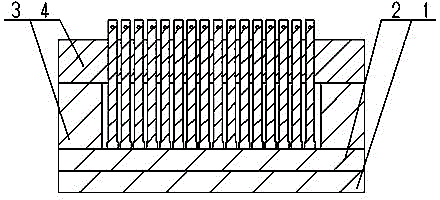
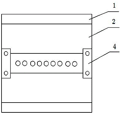
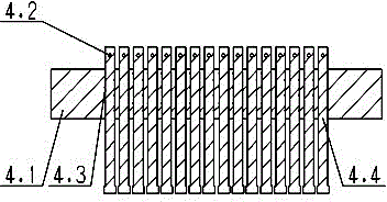
[0028] Embodiment 1: as figure 1 , figure 2 , image 3 , Figure 4 As shown, it is a basic embodiment of a superconducting wire welding device, which includes a heating unit 1, a welding table 2, a heat insulation pad 3 and a pressing unit 4 with a support 4.1; the welding table 2 is fastened On the heating unit 1; the heating unit 1 is provided with a heater and a temperature regulator, and the temperature is precisely adjusted and controlled through a temperature feedback signal; the pressing unit 4 is installed on the welding table 2; the pressing unit 4 also includes: The pressing piece 4.4 on the support body 4.1 is used to apply pressure to the welding joint, and the heat insulation pad 3 is located between the welding table 2 and the support body 4.1. The above-mentioned welding table 2 provides a welding operation plane, which reaches thermal equilibrium with the heating unit 1 after heat conduction and temperature control, and then performs welding operations on t...

Embodiment 2

[0029] Embodiment 2: is an optimized embodiment. like figure 1 As shown in -4, the difference from Example 1 is that the support body 4.1 is a beam, and the pressing member 4.4 is rod-shaped, and there are several; the axes of several holes on the support body 4.1 point to the welding table 2 for the mounting hole of the compression rod; the compression spring 4.3 is sleeved on the compression part 4.4. Compression spring 4.3 Adjust the pressure of the compression member by selecting springs and spring lengths with different stiffness coefficients 4.4 The pressure on the superconducting wire welding joint or the superconducting wire and conventional conductor welding joint, or use hydraulic methods to achieve the required pressure during the welding process .

Embodiment 3

[0030] Embodiment 3: is another optimized embodiment. The difference from the above-mentioned embodiment 2 is that the pressing member 4.4 is a pressing plate, which is slidably connected with the supporting body 4.1. The pressing unit 4 also has a gravity block added to the support body 4.1.


PUM


Abstract

The invention relates a welding device and method for superconducting lines. The welding device comprises a heating unit, a welding bedplate, heat insulation blocks and a pressing unit with a support body, wherein the welding bedplate is fastened on the heating unit; the heating unit is provided with a heater and a temperature adjustor; the pressing unit is mounted on the welding bedplate and further comprises pressing pieces and the heat insulation blocks; and the pressing pieces are mounted on the support body and used for pressing a welding head, and the heat insulation blocks are arranged between the welding bedplate and the support body. The welding device and method for the superconducting lines provided by the invention have the advantages of having a large temperature-controlled range, being high in precision, being capable of meeting the temperature control requirement on the welding of the superconducting lines, and further being capable of improving welding quality and alleviating welding dispersiveness through reducing the thickness of a welding layer, enlarging welding area, lowering welding resistance and reducing artificial operation factors.

Description

technical field [0001] The invention relates to a superconducting wire welding device and a welding method, which is particularly suitable for welding between superconducting wires or between superconducting wires and conventional conductors, and between conventional conductors of certain sizes, and belongs to the technical field of superconducting applications. Background technique [0002] Since the production of superconducting wires is limited by technological conditions, when using superconducting wires to make superconducting magnets, current limiters, cables or other equipment, whether Bi2223, YBCO or MgB , its length cannot be infinitely long, or it can be customized section by section according to engineering needs, and the required length can be solved through the connection of wires. Therefore, the connection technology of wires has become a key technology in practical applications. At present, the general superconducting wire welding method in engineering is res...

Claims


Application Information

Patent Timeline
Patent Type & Authority Patents(China)
IPC IPC(8): B23K3/00B23K3/04B23K3/08H01R43/02
Inventor 苏浩周勇李位勇谢峰
Owner 中国船舶重工集团公司第七一二研究所
Learn More