

Vacuum excrement collection device for passenger train
A vacuum set, train technology, applied in the direction of railway car body parts, sanitary equipment, transportation and packaging, etc., can solve the problems of large compressed air consumption, large compressed air flow, complex control system, etc., to achieve simple structure and save compression Air, noise reduction effect
- Summary
- Abstract
- Description
- Claims
- Application Information
AI Technical Summary
Problems solved by technology
Method used
Image

Examples
Embodiment 1
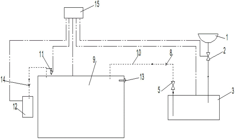
[0018] as attached figure 1 As shown, a vacuum toilet collection device for passenger trains mainly includes a vacuum toilet 1, a vacuum intermediate transition box 3, a dirt terminal collection box 9, a vacuum generating device 12, a PLC controller 15, a vacuum switch 11, a vacuum toilet 1 and a vacuum intermediate The transition box 3 is connected through a pipeline provided with a discharge control valve 2, and the vacuum intermediate transition box 3 is connected with the dirt terminal collection box 9 through a transmission pipeline 10, and the transmission pipeline 10 is provided with a first one-way valve 8, Transmission control valve 5, the transmission control valve 5 is connected to one end of the vacuum intermediate transition box 3, the dirt terminal collection box 9 is connected to the vacuum generating device 12 through a pipeline provided with a second one-way valve 14, the vacuum switch 11 is connected to the dirt terminal The collection box 9 is connected, the...
Embodiment 2
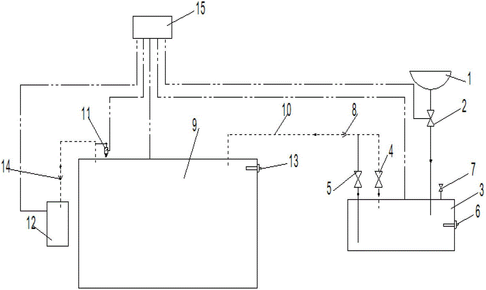
[0020] combine figure 2 , a vacuum toilet collection device for passenger trains, the transmission pipeline 10 is also provided with a vacuum transmission control valve 4, the vacuum transmission control valve 4 is connected to one end of the vacuum intermediate transition box 3, and the transmission control valve 5 is connected in parallel with the vacuum transmission control valve 4. The vacuum intermediate transition box 3 is provided with a vent valve 7, a liquid level sensor I6, and the liquid level sensor I6 and the vent valve 7 are connected to a PLC controller 15, and the PLC controller is a PLC programmable control unit. When the vacuum toilet 1 discharges sewage, the PLC controller 15 controls the discharge control valve 2 to open to allow the dirt to enter the vacuum intermediate transition box 3, otherwise the discharge control valve 2 is closed to prevent system vacuum leakage. After the vacuum intermediate transition box 3 receives the dirt once, that is, after ...
PUM
 Abstract
Description
Claims
Application Information