Method for remotely exciting micrometer-scale micro-cantilever probe to resonate by using laser

A technology of micro-cantilever and remote excitation, which is applied in the direction of material analysis, instruments, and measuring devices through optical means. simple effect

Inactive Publication Date: 2013-02-27
SHANDONG UNIV
View PDF3 Cites 6 Cited by
  • Summary
  • Abstract
  • Description
  • Claims
  • Application Information

AI Technical Summary

Problems solved by technology

A common disadvantage of traditional excitation techniques is that none of them are "non-contact" excitation methods, because in these excitation methods, the microcantilever must be bound to a piezoelectric transducer (or other mechanical oscillator), electrodes, or permanent on the magnet
However, ultrasonic excitation has two important disadvantages compared to laser excitation: (1) It is difficult to achieve focusing
The

Method used


Image

  • Method for remotely exciting micrometer-scale micro-cantilever probe to resonate by using laser
  • Method for remotely exciting micrometer-scale micro-cantilever probe to resonate by using laser
  • Method for remotely exciting micrometer-scale micro-cantilever probe to resonate by using laser

Examples


Embodiment 1

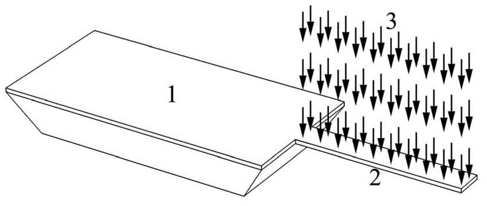
[0025] Such as figure 1 shown. According to claim 1, a method for remotely exciting the resonance of a micron-scale micro-cantilever probe using a laser, using a Zhousi pulse laser 3 to focus on the surface of the micro-cantilever probe 2, through the thermal effect of the laser on the micro-cantilever probe 2 The thermal stress generated in the cantilever probe 2 realizes the resonant excitation of the micro-scale micro-cantilever probe.

[0026] The length of the micro-scale micro-cantilever probe 2 is 100 μm; the width is 10 μm; the thickness is 1 μm. The wavelength of the pulsed laser 3 is 405 nm, and the frequency of the pulsed laser 3 is the 1 / 7 of the resonant frequency.

Embodiment 2

[0028] According to claim 1, a method for remotely exciting the resonance of a micron-scale micro-cantilever beam probe using a laser, its structure and excitation method are the same as those in Example 1, except that:

[0029] The length of the micro-cantilever probe on the micrometer scale is 300 μm; the width is 35 μm; the thickness is 1 μm, the wavelength of the pulsed laser is 532 nm, and the frequency of the pulsed laser is the resonant frequency of the micro-cantilever probe 1 / 5.

Embodiment 3

[0031] According to claim 1, a method for remotely exciting the resonance of a micron-scale micro-cantilever beam probe using a laser, its structure and excitation method are the same as those in Example 1, except that:

[0032] The length of the micro-cantilever probe on the micrometer scale is 500 μm; the width is 50 μm; the thickness is 2 μm, the wavelength of the pulsed laser is 650 nm, and the frequency of the pulsed laser is the resonant frequency of the micro-cantilever probe 1 / 3.

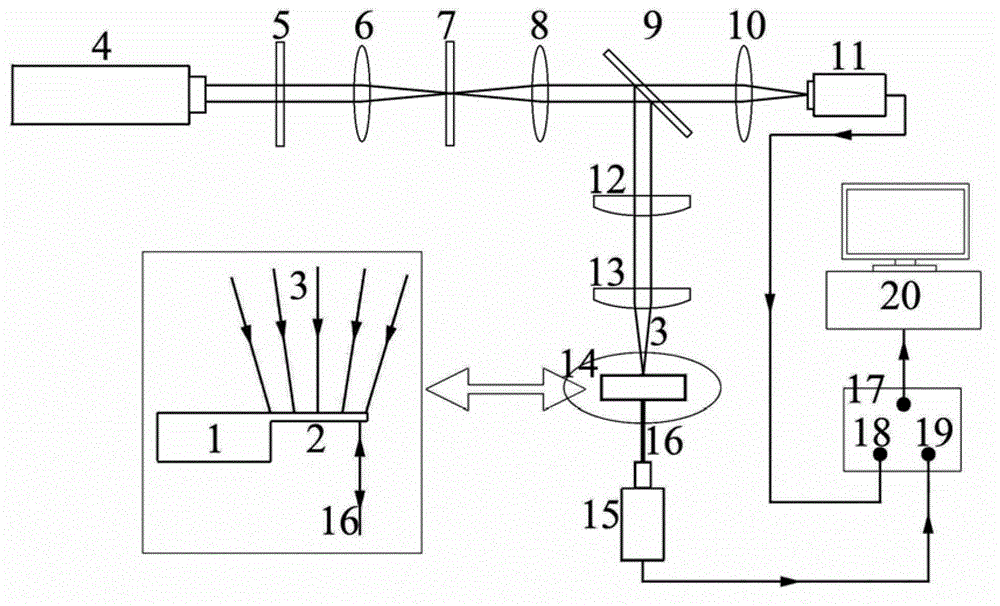
[0033] Such as figure 2 shown. In order to achieve the above-mentioned remote excitation of the micro-cantilever beam probe resonance with laser, the following excitation device is used:

[0034] The excitation device includes a laser emitting device and a micro-cantilever, and the micro-cantilever includes a micro-cantilever base 1 and a micro-cantilever probe 2 of the same material as one with the micro-cantilever base 1;

[0035]Described laser emitting device comprises continuous las...


PUM

PropertyMeasurementUnit
Wavelengthaaaaaaaaaa

Abstract

The invention relates to a method for remotely exciting micrometer-scale micro-cantilever probes to resonate by using laser. By applying pulse laser with certain frequency for radiation onto surfaces of the micrometer-scale micro-cantilever probes and producing thermal stress in the micrometer-scale micro-cantilever probes under the thermal effect of the laser, the resonance excitation of the micrometer-scale micro-cantilever probes is realized. The frequency of the pulse laser is 1/n of the resonance frequency of the micro-cantilever probes, wherein n is a number within 1-10. The micrometer-scale micro-cantilever probes are excited to resonate by using n-order Fourier harmonic waves of the thermal stress produced in the micro-cantilever probes under the thermal effect of the laser.

Description

technical field [0001] The invention relates to a method for remotely exciting the resonance of a micro-cantilever beam probe with a laser beam, and belongs to the technical field of micro-electromechanical systems. Background technique [0002] Microcantilever sensors are widely used in the measurement of weak signals today, and the substances that can be used for detection include mercury vapor, hydrogen fluoride gas, TNT explosives, DNA, protein molecules, etc. Its working principle is to realize detection by changing the motion state of the probe through the surface adsorption of the micro-cantilever beam probe to the target molecule. It has the advantages of fast speed, high precision and good repeatability. The core technology in the sensing process is how to realize the resonance excitation of the micro-cantilever beam probe, which has an important impact on the application range, response speed and detection accuracy of the sensor. [0003] Traditional excitation te...

Claims


Application Information

Patent Timeline
IPC IPC(8): G01N30/00G01N21/00
Inventor 刘铎冯兆斌
Owner SHANDONG UNIV
Why Eureka
Try Eureka