Infrared marker for detecting heating of electric equipment

A live equipment, infrared technology, applied in the field of infrared marking, can solve the problems of the surface conditions of the heating parts of electrical equipment vary greatly, reduce the accuracy and efficiency of measurement, and cannot cover all phenomena, etc., to achieve easy detection range, convenient storage and reference, and improve monitoring efficiency effect

Inactive Publication Date: 2013-03-06
国网四川省电力公司技能培训中心 +1
View PDF6 Cites 3 Cited by
  • Summary
  • Abstract
  • Description
  • Claims
  • Application Information

AI Technical Summary

Problems solved by technology

But there are the following three problems: 1. The surface conditions of the heating parts of electrical equipment vary widely, such as the new and old layers of the surface, cleaning conditions, etc., which directly affect an important indicator of infrared imaging temperature monitoring: emissivity
Now the emissivity is estimated by the staff based on experience. "Guidelines for the Application of Infrared Diagnosis Technology for Live Equipment" DL / T 664-2008 recommends the method of estimating the surface emissivity of typical materials. Although it is detailed, it cannot be comprehensive. Staff must undergo special training and long-term practice before they can use their methods
2. There are many types of power equipment. There are similar equipment in different intervals of the same substation. All equipment has a number, but it is not in the heat-generating parts detected by the infrared imager, such as contacts, busbar connections, etc. Generally, there is no equipment number. The staff is Only other methods can be used to record the reflected part of the infrared image, such as voice, notes, etc.
Not direct, error-prone; 3. In actual infrared imaging monitoring, the emissivity of the part captured by the previous image may be quite different from that of the next image. Accurate measurement needs to constantly set the emissivity of the infrared imager, which will Reduce measurement accuracy and efficiency

Method used


Image

  • Infrared marker for detecting heating of electric equipment
  • Infrared marker for detecting heating of electric equipment
  • Infrared marker for detecting heating of electric equipment

Examples


Embodiment Construction

[0011] The following will be described in conjunction with the accompanying drawings and specific embodiments.

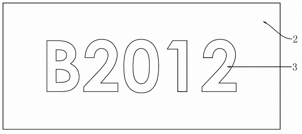
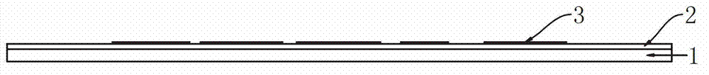
[0012] see figure 1 and figure 2 . The infrared marking used for heating detection of charged equipment described in the present invention has a structure as follows: an infrared material layer 2 is coated on a PET film 1, and an anodized aluminum foil mark 3 is also attached on the PET film 1, and the infrared material layer 2 and The anodized aluminum foil mark 3 is on the same side of the PET film 1 . The infrared material layer 2 is an infrared material layer with a matte gloss of 5-7 and a surface emissivity of not less than 0.95. Anodized aluminum foil mark 3 is an anodized aluminum foil text mark with a surface emissivity of 0.02. The text mark can be a letter number, a number number, or a combination of letters and numbers.

[0013] The emissivity of the PET film product used in the present invention is 0.87, and the emissivity is fixed at 0.95 after th...


PUM

PropertyMeasurementUnit
densityaaaaaaaaaa
emissivityaaaaaaaaaa

Abstract

The invention discloses an infrared marker for detecting heating of electric equipment. The infrared maker is structurally characterized in that a PET (polyethylene terephthalate) thin film is coated with an infrared material layer, the PET thin film is also attached with an electrified aluminum foil marker, and the infrared material layer and the electrified aluminum foil marker are arranged on the same surface of the PET thin film. Compared with the prior art, the infrared marker has the advantages that the surface emissivity of the detection part of the electric equipment is not less than 0.95, the temperature precision of the infrared detection is improved, the setting of the emissivity of an infrared imaging instrument is reduced, and the monitoring efficiency is improved; and when the electrified aluminum foil marker is used, the convenience in recording is realized, and meanwhile, the detection range can be conveniently verified.

Description

technical field [0001] The invention relates to a mark used for temperature detection, in particular to an infrared mark applied to temperature distribution detection of charged equipment by temperature measuring instruments such as infrared imagers. Background technique [0002] Infrared imagers and other temperature measuring instruments have been widely and maturely used in the diagnosis of fever. Since the detection of fault points is non-contact and electrified, the diagnosis of potential thermal faults of power equipment has high efficiency, accurate judgment, and image Intuitive, safe and reliable, free from electromagnetic interference, long detection distance and fast detection speed, etc., make early fault diagnosis and preventive maintenance of electrical equipment simple and convenient. But there are the following three problems: 1. The surface conditions of the heating parts of electrical equipment vary widely, such as the new and old layers of the surface, clea...

Claims


Application Information

Patent Timeline
Patent Type & Authority Applications(China)
IPC IPC(8): G01J5/00
Inventor 张德威邹慧肖兰
Owner 国网四川省电力公司技能培训中心
Why Eureka
Try Eureka